FWS 1206 C

FWS 1206 C
- Detects standstill using 1 or 2 impulse sensors
- Uses additional standstill signal, e.g. PLC as second input channel
- 2 safety contacts
- 2 Signalling outputs
Ordering data
| Note (Delivery capacity) |
Phased-out product |
| Product type description |
FWS 1206 C |
| Article number (order number) |
101170058 |
| EAN (European Article Number) |
4030661297200 |
| eCl@ss number, version 12.0 |
27-37-18-19 |
| eCl@ss number, version 11.0 |
27-37-18-19 |
| eCl@ss number, version 9.0 |
27-37-18-19 |
| ETIM number, version 7.0 |
EC001449 |
| ETIM number, version 6.0 |
EC001449 |
| Available until |
31.12.2024 |
Approvals - Standards
| Certificates |
cULus |
General data
| Standards |
BG-GS-ET-20 EN IEC 62061 EN ISO 13849-1 EN IEC 60947-5-1 EN IEC 60947-5-3 EN IEC 60947-5-5 EN IEC 60204-1 EN IEC 60947-1 |
| Climatic stress |
EN 60068-2-3 BG-GS-ET-14 |
| Housing material |
Tworzywo, Tworzywo termoplastyczne wzmocnione włóknem szklanym, obudowa wentylowana |
| Gross weight |
200 g |
General data - Features
| Wire breakage detection |
Tak |
| Feedback circuit |
Tak |
| Reset edge detection |
Tak |
| Earth connection detection |
Tak |
| Integral system diagnostics, status |
Tak |
| Number of LEDs |
1 |
| Number of undelayed semi-conductor outputs with signaling function |
2 |
| Number of safety contacts |
2 |
| Number of signalling outputs |
2 |
| Safety classification |
| Vorschriften |
EN IEC 61508 |
| Performance Level, up to |
d |
| Category |
3 |
| PFH value |
1,00 x 10⁻⁷ /h |
| Safety Integrity Level (SIL), suitable for applications in |
2 |
| Mission time |
20 Year(s) |
| Stop-Category |
0 |
Mechanical data
| Mechanical lifetime, minimum |
20.000.000 Operations |
| Mounting |
montaż na standardowej szynie DIN wg EN 60715 |
Mechanical data - Connection technique
| Terminal designations |
IEC/EN 60947-1 |
| Termination |
sztywny lub elastyczny Połączenie śrubowe M20 x 1.5 |
| Cable section, minimum |
0,2 mm² |
| Cable section, maximum |
2,5 mm² |
| Tightening torque of Clips |
0,6 Nm |
Mechanical data - Dimensions
| Width |
22,5 mm |
| Height |
100 mm |
| Depth |
121 mm |
Ambient conditions
| Degree of protection of the enclosure |
IP40 |
| Degree of protection of the installation space |
IP54 |
| Degree of protection of clips or terminals |
IP20 |
| Ambient temperature |
+0 ... +55 °C |
| Storage and transport temperature |
-25 ... +70 °C |
| Resistance to vibrations |
10 ... 55 Hz, amplituda 0,35 mm |
| Restistance to shock |
30 g / 11 ms |
Ambient conditions - Insulation values
| Rated impulse withstand voltage Uimp |
4,8 kV |
| Overvoltage category |
II |
| Degree of pollution |
3 |
Electrical data
| Operating voltage |
24 VDC -15 % / +15 % |
| Thermal test current |
6 A |
| Rated operating voltage |
24 VDC |
| Rated AC voltage for controls, 50 Hz, minimum |
20.4 VAC |
| Rated control voltage at AC 50 Hz, maximum |
26.4 VAC |
| Rated AC voltage for controls, 60 Hz, minimum |
20.4 VAC |
| Rated control voltage at AC 60 Hz, maximum |
26.4 VAC |
| Rated AC voltage for controls at DC minimum |
20,4 VDC |
| Rated control voltage at DC, maximum |
28,8 VDC |
| Electrical power consumption, maximum |
5 W |
| Contact resistance, maximum |
0,1 Ω |
| Note (Contact resistance) |
w nowym stanie |
| Material of the contacts, electrical |
Ag-Ni 10 pozłacane 0,2 µm |
Electrical data - Safe relay outputs
| Voltage, Utilisation category AC-15 |
230 VAC |
| Current, Utilisation category AC-15 |
3 A |
| Voltage, Utilisation category DC-13 |
24 VDC |
| Current, Utilisation category DC-13 |
2 A |
| Switching capacity, minimum |
10 VDC |
| Switching capacity, minimum |
10 mA |
| Switching capacity, maximum |
250 VAC |
| Switching capacity, maximum |
8 A |
Electrical data - Digital inputs
| Input signal, HIGH Signal "1" |
10 … 30 VDC |
| Input signal, LOW Signal "0" |
0 … 2 VDC |
| Conduction resistance, maximum |
40 Ω |
Electrical data - Relay outputs (auxiliary contacts)
| Switching capacity, maximum |
24 VDC |
| Switching capacity, maximum |
2 A |
Integral system diagnosis (ISD)
| Note (ISD -Faults) |
Następujące błędy zostały zarejestrowane przez moduły bezpieczeństwa i wskazane przez ISD. |
| Faults |
Błąd załączenia lub wyłączenia przekaźnika bezpieczeństwa Niezadziałanie obwodów wejściowych lub obwodów przekaźnikowych sterowania modułu monitorującego bezpieczeństwa Niezadziałanie wyłączników zbliżeniowych Niepowodzenie analizy jednego kanału Przerwanie połączeń do indukcyjnych wyłączników zbliżeniowych |
Other data
| Note (applications) |
Bezpieczna kontrola bezruchu |
Note
| Note (General) |
Obciążenia indukcyjne (np. styczniki, przekaźniki itp.) należy wytłumić przy pomocy odpowiedniego obwodu. |
Wiring example
| Note (Wiring diagram) |
Jeżeli do modułu z wykrywaniem bezruchu podłączony jest tylko jeden indukcyjny wyłącznik zbliżeniowy, częstotliwości bezczynności muszą być identyczne i wyjścia X1 oraz X2 muszą być zmostkowane. |
Filtr językowy
Karta katalogowa
Instrukcja obsługi i deklaracja zgodności
Certyfikat UL
Info
Przykład połączeń (okablowanie elektryczne)
Biblioteka/Library SISTEMA-VDMA
pobierz najnowszą wersję Adobe Reader
Zdjęcie produktu (pojedyncze zdjęcie katalogowe)
Przykład okablowania

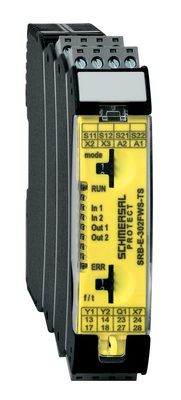
103014754 SRB-E-302FWS-TS
- 2 Safety contacts, 1 Safety Output
- Plug-in screw terminals with coding
- 1 Signalling output - status safety module
- 1 Signalling output - failure massage dynamic
- Detects standstill using 1 or 2 impulse sensors
- additional standstill signal, e.g. PLC as second input channel
- 2-channel time monitoring
| EU Declaration of Conformity |  |
| Original | K.A. Schmersal GmbH & Co. KG Möddinghofe 30 42279 Wuppertal Germany Internet: www.schmersal.com |
| Declaration: | We hereby certify that the hereafter described components both in their basic design and construction conform to the applicable European Directives. |
| Name of the component: | FWS 1206 |
| Type: | See ordering code |
| Description of the component: | Fail-safe standstill monitor |
| Relevant Directives: | Machinery Directive | 2006/42/EC |
| EMC-Directive | 2014/30/EU | |
| RoHS-Directive | 2011/65/EU |
| Applied standards: | EN 60947-5-1:2017 + AC:2020 EN ISO 13849-1: 2015 EN ISO 13849-2: 2012 |
| Notified body, which approved the full quality assurance system, referred to in Appendix X, 2006/42/EC: | TÜV Rheinland Industrie Service GmbH Am Grauen Stein, 51105 Köln ID n°: 0035 |
| Person authorised for the compilation of the technical documentation: | Oliver Wacker Möddinghofe 30 42279 Wuppertal |
| Place and date of issue: | Wuppertal, August 4, 2023 |
 |
| Authorised signature Philip Schmersal Managing Director |
Schmersal India Pvt. Ltd., Plot No - G-7/1, Ranjangaon MIDC, Tal. - Shirur, Dist.- Pune 412 220
Dane zostały starannie sprawdzone. Zdjęcia mogą odbiegać od rzeczywistości. Dalsze dane techniczne znajdują się w instrukcji obsługi. Możliwe są zmiany i błędy techniczne.
Wygenerowano dnia 25.08.2025, 16:46