SRB202MSL
SRB202MSL
Descargas
- Muting signalling device monitoring
- 2 safety contacts, STOP 0
- 2 Signalling outputs
Ordering data
| Note (Delivery capacity) |
No más disponible! |
| Product type description |
SRB202MSL |
| Article number (order number) |
101181998 |
| EAN (European Article Number) |
4250116202577 |
| eCl@ss number, version 12.0 |
27-37-18-19 |
| eCl@ss number, version 11.0 |
27-37-18-19 |
| eCl@ss number, version 9.0 |
27-37-18-19 |
| ETIM number, version 7.0 |
EC001449 |
| ETIM number, version 6.0 |
EC001449 |
General data
| Standards |
EN IEC 62061 EN ISO 13849-1 EN IEC 60947-5-1 EN IEC 60947-5-3 EN IEC 60947-5-5 EN IEC 61508 EN IEC 60204-1 EN IEC 60947-1 |
| Climatic stress |
EN 60068-2-78 |
| Housing material |
Plástico reforzado con fibra de vidrio, ventilador |
| Gross weight |
400 g |
General data - Features
| Electronic Fuse |
Sí |
| Wire breakage detection |
Sí |
| Cross-circuit detection |
Sí |
| Removable Terminals |
Sí |
| Feedback circuit |
Sí |
| Automatic reset function |
Sí |
| Reset after disconnection of supply voltage |
Sí |
| Earth connection detection |
Sí |
| Integral system diagnostics, status |
Sí |
| Number of auxiliary contacts |
2 |
| Number of LEDs |
8 |
| Number of normally closed (NC) |
2 |
| Number of safety contacts |
2 |
| Number of signalling outputs |
2 |
| Safety classification |
| Vorschriften |
EN IEC 60947-5-1 EN IEC 61508 |
| Stop-Category |
0 |
| Safety classification - Relay outputs |
| Performance Level, stop 0, up to |
e |
| Category, Stop 0 |
4 |
| Diagnostic Coverage (DC) Level, Stop 0 |
≥ 99 % |
| PFH value, Stop 0 |
2,00 x 10⁻⁸ /h |
| Safety Integrity Level (SIL), Stop 0, suitable for applications in |
3 |
| Mission time |
20 Year(s) |
| Common Cause Failure (CCF), minimum |
65 |
Mechanical data
| Mechanical life, minimum |
10.000.000 Operations |
| Mounting |
Sujeción rápida para carriles normalizados según DIN EN 60715 |
Mechanical data - Connection technique
| Terminal designations |
IEC/EN 60947-1 |
| Termination |
rígido o flexible Terminales con tornillo M20 x 1.5 |
| Cable section, minimum |
0,25 mm² |
| Cable section, maximum |
2,5 mm² |
| Tightening torque of Clips |
0,6 Nm |
Mechanical data - Dimensions
| Width |
45 mm |
| Height |
100 mm |
| Depth |
121 mm |
Ambient conditions
| Degree of protection of the enclosure |
IP40 |
| Degree of protection of the mounting space |
IP54 |
| Degree of protection of clips or terminals |
IP20 |
| Ambient temperature |
-25 ... +45 °C |
| Storage and transport temperature |
-40 ... +85 °C |
| Resistance to vibrations |
10...55 Hz, amplitud 0,35 mm, ± 15 % |
| Restistance to shock |
30 g / 11 ms |
Ambient conditions - Insulation values
| Rated impulse withstand voltage Uimp |
4 kV |
| Overvoltage category |
III |
| Degree of pollution |
2 |
Electrical data
| Frequency range |
50 Hz 60 Hz |
| Operating voltage |
24 VDC -10 % / +20 % |
| Ripple voltage |
10 % |
| Rated operating voltage |
24 VDC |
| Rated AC voltage for controls at DC minimum |
20,4 VDC |
| Rated control voltage at DC, maximum |
28,8 VDC |
| Utilisation category DC-13 |
24 VDC |
| Utilisation category DC-13 |
2 A |
| Electrical power consumption |
5,6 W |
| Contact resistance, maximum |
0,1 Ω |
| Note (Contact resistance) |
en estado nuevo |
| Drop-out delay in case of power failure, typically |
60 ms |
| Drop-out delay in case of emergency, typically |
17 ms |
| Drop-out delay in case of "emergency stop", maximum |
20 ms |
| Pull-in delay at automatic start, maximum, typically |
200 ms |
| Material of the contacts, electrical |
AgSn0, Ag-Ni, autolimpiante, guiado monitorizado |
Electrical data - Digital inputs
| Conduction resistance, maximum |
40 Ω |
Electrical data - Electromagnetic compatibility (EMC)
| EMC rating |
Directiva sobre compatibilidad electromagnética CEM |
Status indication
| Indicated operating states |
Posición de los relés K2 Posición de ls relés K1 Tensión de servicio interna Ui Posición de los relés K3 Posición de los relés K5 Posición del dispositivo de señalización de muting LA |
Other data
| Note (applications) |
Función muting |
Note
| Note (General) |
Obciążenia indukcyjne (np. styczniki, przekaźniki itp.) należy wytłumić przy pomocy odpowiedniego obwodu. |
Wiring example
| Note (Wiring diagram) |
Campos de potencia: diseñado para control de 2 canales, para reforzar los contactos, o bien para ampliar su número, utilizar contactores o relés con los contactos de guía forzada. El control detecta cruces entre hilos, roturas de cable y cortocircuitos a tierra del circuito de monitorización. El ejemplo demuestra un circuito de control de 2 canales con 2 sensores de muting y un pulsador prioritario externo. El dibujo muestra los sensores de muting no activados y sin alimentación. (H2) = Circuito de realimentación F1 = Fusible electrónico |
Filtro de idiomas
Ficha técnica
Instrucciones de montaje e instalación
Manual de instrucciones y declaración de conformidad
Ejemplo de cableado (cableado eléctr.)
Descargar la versión actual de Adobe Reader
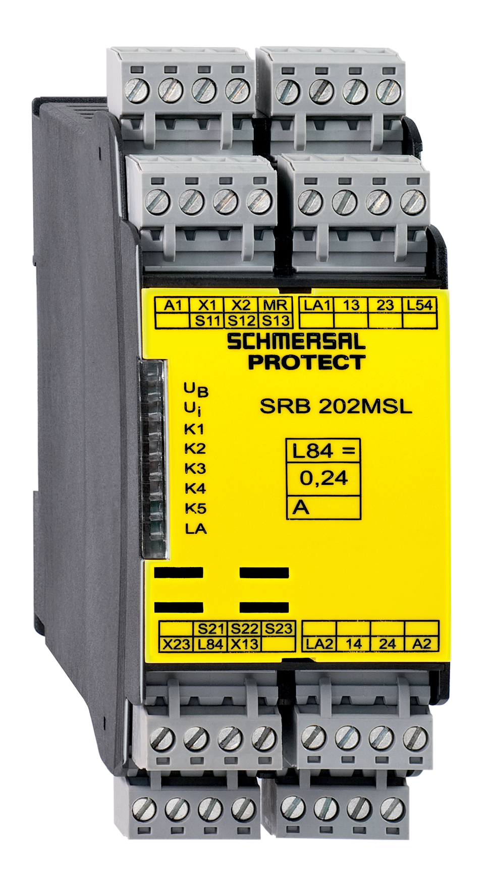
Foto de producto (foto individual de catálogo)
Ejemplo de cableado

Símbolo (estandar técnico)

Schmersal India Pvt. Ltd., Plot No - G-7/1, Ranjangaon MIDC, Tal. - Shirur, Dist.- Pune 412 220
Los datos e información anteriores se han verificado cuidadosamente. Las imágenes pueden diferir del original. Se pueden encontrar más datos técnicos en los manuales de instrucciones. Sujeto a cambios técnicos y errores.
Generado a 25/3/2025 1:20