TR 335 ST-AS

TR 335 ST-AS
- AS-Interface M12 connector
- Metal enclosure
- Wide range of alternative actuators
- Good resistance to oil and petroleum spirit
- 40,5 mm x 96 mm x 38 mm
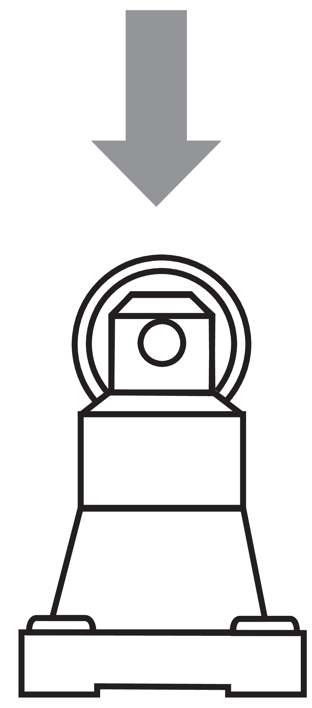
- Actuator heads can be repositioned by 4 x 90°
- Mounting details to EN 50047
- AS-Interface LED and status display
- Integrated AS-Interface
- Suitable for AS-i Power24
Ordering data
| Note (Delivery capacity) |
Nicht mehr lieferbar! |
| Product type description |
TR 335 ST-AS |
| Article number (order number) |
101213983 |
| EAN (European Article Number) |
4030661404189 |
| eCl@ss number, version 12.0 |
27-27-26-01 |
| eCl@ss number, version 11.0 |
27-27-26-01 |
| eCl@ss number, version 9.0 |
27-27-26-01 |
| ETIM number, version 7.0 |
EC000030 |
| ETIM number, version 6.0 |
EC000030 |
Approvals - Standards
| Certificates |
cULus ASi-SaW |
General data
| Standards |
EN 50295 EN ISO 13849-1 EN IEC 60947-5-1 EN IEC 61508 |
| Housing construction form |
Normbauform |
| Actuator type to EN 50041 |
C |
| Housing material |
Metall, Zink-Druckguss |
| Housing coating material |
lackiert |
| Gross weight |
215 g |
General data - Features
| Safety functions |
Ja |
| Integral system diagnostics, status |
Ja |
| Number of safety contacts |
2 |
| Safety classification |
| Vorschriften |
EN IEC 61508 |
| Performance Level, up to |
c |
| Category |
1 |
| PFH value |
1,14 x 10⁻⁶ /h |
| Note (PFH-value) |
bis max. 100.000 Schaltzyklen/Jahr |
| Safety Integrity Level (SIL), suitable for applications in |
1 |
| Mission time |
20 Year(s) |
| Safety classification - Fault exclusion |
| Please note: |
Einsetzbar wenn ein Fehlerausschluss für eine gefahrbringende Beschädigung der 1-kanaligen Mechanik zulässig ist und ein ausreichender Manipulationsschutz gewährleistet ist. |
| Performance Level, up to |
d |
| Category |
3 |
| PFH value |
1,01 x 10⁻⁷ /h |
| Note (PFH-value) |
bis max. 100.000 Schaltzyklen/Jahr |
| Safety Integrity Level (SIL), suitable for applications in |
2 |
| Mission time |
20 Year(s) |
Mechanical data
| Actuating element |
Rollendruckbolzen |
| Mechanical life, minimum |
1.000.000 Operations |
| Actuating speed, maximum |
0,5 m/s |
| Note (Actuating speed) |
Betätigungsgeschwindigkeit bei einem vertikalen Anfahrwinkel von 30° |
Mechanical data - Connection technique
| Termination |
Einbaustecker M12, 5-polig, drehbar |
| Material of the connector (electrical) |
Metall |
Mechanical data - Dimensions
| Length of sensor |
38 mm |
| Width of sensor |
40,5 mm |
| Height of sensor |
136,6 mm |
Ambient conditions
| Degree of protection |
IP67 |
| Ambient temperature |
-25 ... +60 °C |
| Storage and transport temperature |
-25 ... +85 °C |
| Relative humidity, minimum |
30 % |
| Relative humidity, maximum |
95 % |
| Note (Relative humidity) |
nicht kondensierend nicht vereisend |
| Resistance to vibrations |
10 … 150 Hz, Amplitude 0,35 mm / 5 g |
| Restistance to shock |
30 g / 11 ms |
Ambient conditions - Insulation values
| Rated insulation voltage Ui |
32 VDC |
| Rated impulse withstand voltage Uimp |
0,8 kV |
Electrical data
| Current consumption |
50 mA |
| Thermal test current |
10 A |
| Utilisation category AC-15 |
230 VAC |
| Utilisation category AC-15 |
4 A |
| Utilisation category DC-13 |
24 VDC |
| Utilisation category DC-13 |
1 A |
| Switching element |
Öffner (NC) |
| Switching principle |
Schleichschaltung |
| Maximale Schalthäufigkeit |
5.000 /h |
| Material of the contacts, electrical |
Silber |
Electrical data - AS Interface
| Rated operating voltage |
18 ... 31,6 VDC (Verpolungsschutz) |
Electrical data - AS-Interface specification
| AS-i Version |
V 3.0 |
| AS-i Profile |
S-0.B.F.F |
| AS-i Input, Channel 1 |
Datenbits DI 0/DI 1 = dynamische Codeübertragung |
| AS-i Input, Channel 2 |
Datenbits DI 2/DI 3 = dynamische Codeübertragung |
| AS-i Outputs, DO 0 … DO 3 |
Keine Funktion |
| AS-i Parameter bits, P0 |
Kanal 2 geschaltet |
| AS-i Parameter bits, P1 ... P3 |
Keine Funktion |
| AS-i Input module address |
0 |
| Note (AS-i Input module address) |
Voreingestellt auf Adresse 0, änderbar über AS-Interface Busmaster oder Handprogrammiergerät |
Status indication
| Note (LED switching conditions display) |
(1) gelbe LED: Kanal 1 / AS-i SaW Bit 0.1 (2) grün/rote LED (AS-i Duo LED): Versorgungsspannung / Kommunikationsfehler / Slaveadresse = 0 (3) gelbe LED: Kanal 2 / AS-i SaW Bit 2.3 |
Pin assignment
| PIN 1 |
AS-Interface + |
| PIN 2 |
n.c. |
| PIN 3 |
AS-Interface - |
| PIN 4 |
n.c. |
| PIN 5 |
Funktionserde |
Sprachfilter
Datenblatt
Betriebsanleitung und Konformitätserklärung
UL-Zertifikat
AS-Interface at Work Zertifikat
SISTEMA-VDMA Bibliothek/Library
Download der aktuellen Version von Adobe Reader
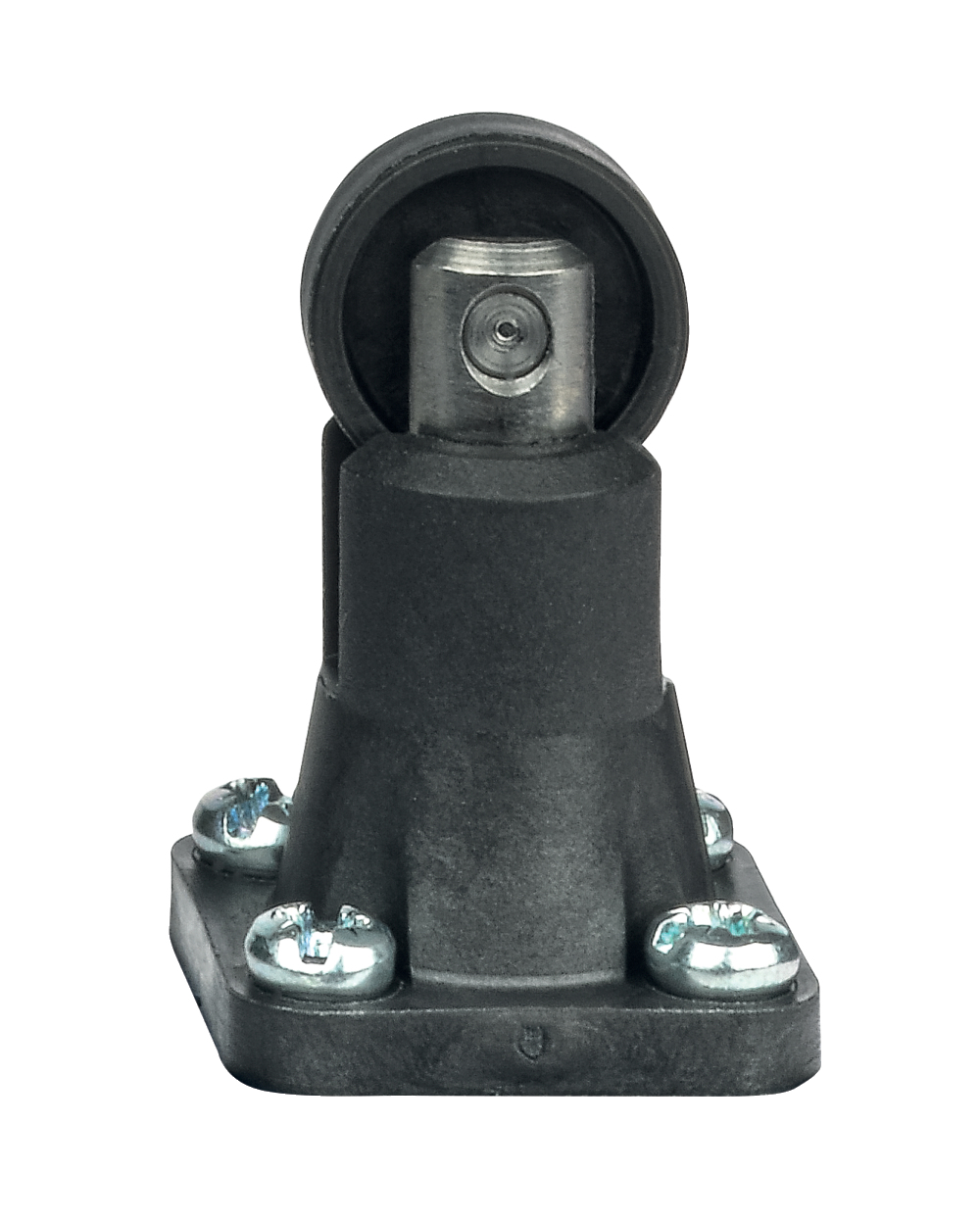
Produktbild (Katalogeinzelphoto )
Produktbild (Katalogeinzelphoto )
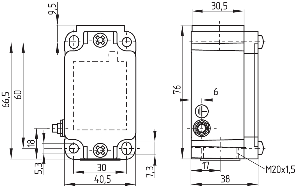
Maßzeichnung Grundgerät
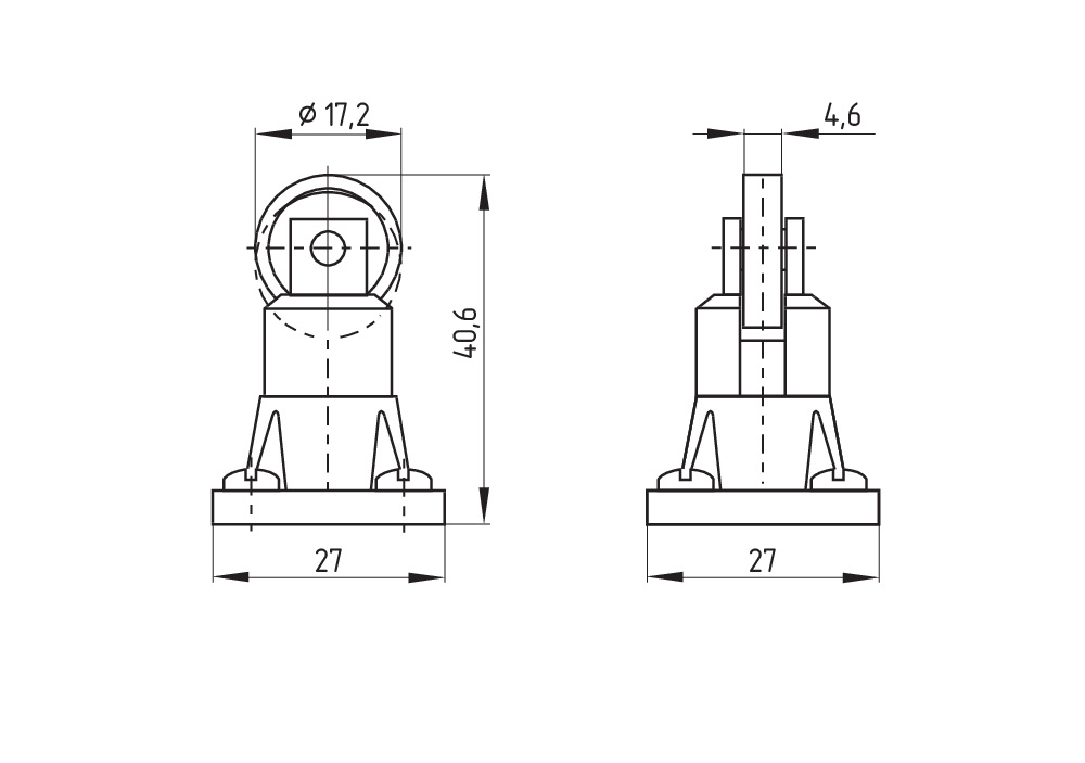
Maßzeichnung Betätiger
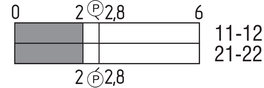
Schaltwegdiagramm
Funktionsweise

Schmersal India Pvt. Ltd., Plot No - G-7/1, Ranjangaon MIDC, Tal. - Shirur, Dist.- Pune 412 220
Die genannten Daten und Angaben wurden sorgfältig geprüft. Abbildungen können vom Original abweichen. Weitere technische Daten finden Sie in der Betriebsanleitung. Technische Änderungen und Irrtümer vorbehalten.
Generiert am: 09.04.2025, 03:39