TR 335 ST-AS
TR 335 ST-AS
- AS-Interface M12 connector
- Metal enclosure
- Wide range of alternative actuators
- Good resistance to oil and petroleum spirit
- 40,5 mm x 96 mm x 38 mm
- Actuator heads can be repositioned by 4 x 90°
- Mounting details to EN 50047
- AS-Interface LED and status display
- Integrated AS-Interface
- Suitable for AS-i Power24
Ordering data
| Note (Delivery capacity) |
Not available! |
| Product type description |
TR 335 ST-AS |
| Article number (order number) |
101213983 |
| EAN (European Article Number) |
4030661404189 |
| eCl@ss number, version 12.0 |
27-27-26-01 |
| eCl@ss number, version 11.0 |
27-27-26-01 |
| eCl@ss number, version 9.0 |
27-27-26-01 |
| ETIM number, version 7.0 |
EC000030 |
| ETIM number, version 6.0 |
EC000030 |
Approvals - Standards
| Certificates |
cULus ASi-SaW |
General data
| Standards |
EN 50295 EN ISO 13849-1 EN IEC 60947-5-1 EN IEC 61508 |
| Housing construction form |
Norm construction design |
| Actuator type to EN 50041 |
C |
| Housing material |
Metal, zinc die-cast |
| Housing coating material |
painted |
| Gross weight |
215 g |
General data - Features
| Safety functions |
Yes |
| Integral system diagnostics, status |
Yes |
| Number of safety contacts |
2 |
| Safety classification |
| Standards |
EN IEC 61508 |
| Performance Level, up to |
c |
| Category |
1 |
| PFH value |
1.14 x 10⁻⁶ /h |
| Note (PFH-value) |
up to max. 100,000 switching cycles/year |
| Safety Integrity Level (SIL), suitable for applications in |
1 |
| Mission time |
20 Year(s) |
| Safety classification - Fault exclusion |
| Please note: |
Can be used when fault exclusion for dangerous damage to the 1-channel mechanism is permissible and sufficient protection against manipulation is guaranteed. |
| Performance Level, up to |
d |
| Category |
3 |
| PFH value |
1.01 x 10⁻⁷ /h |
| Note (PFH-value) |
up to max. 100,000 switching cycles/year |
| Safety Integrity Level (SIL), suitable for applications in |
2 |
| Mission time |
20 Year(s) |
Mechanical data
| Actuating element |
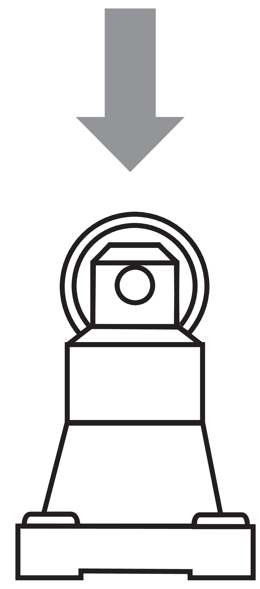
Roller plunger |
| Mechanical lifetime, minimum |
1,000,000 Operations |
| Actuating speed, maximum |
0.5 m/s |
| Note (Actuating speed) |
Actuating speed with actuating angle 30° to switch axis |
Mechanical data - Connection technique
| Termination |
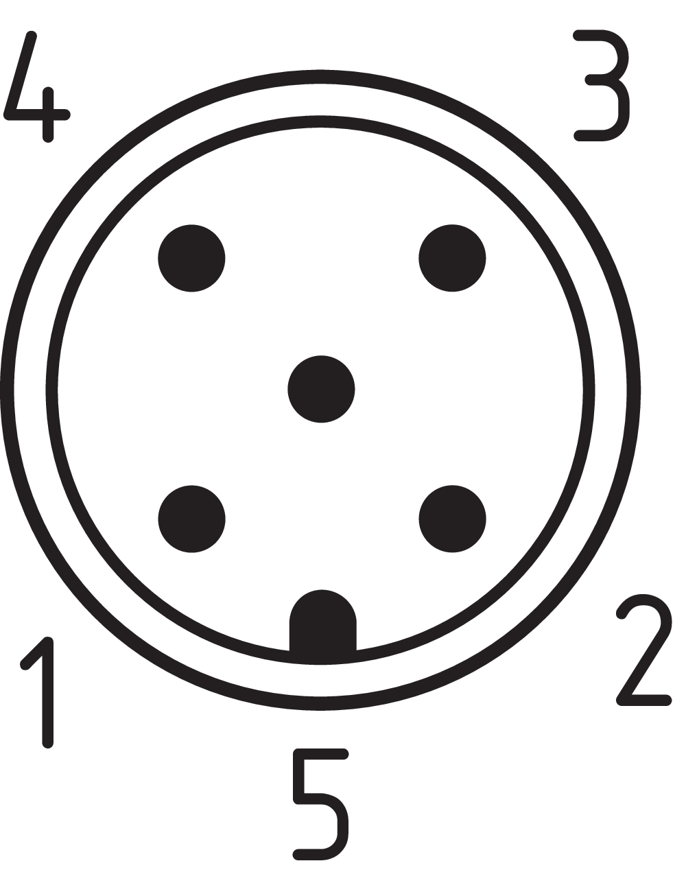
Connector plug M12, 5-pole, can be rotated |
| Material of the connector (electrical) |
Metal film |
Mechanical data - Dimensions
| Length of sensor |
38 mm |
| Width of sensor |
40.5 mm |
| Height of sensor |
136.6 mm |
Ambient conditions
| Degree of protection |
IP67 |
| Ambient temperature |
-25 ... +60 °C |
| Storage and transport temperature |
-25 ... +85 °C |
| Relative humidity, minimum |
30 % |
| Relative humidity, maximum |
95 % |
| Note (Relative humidity) |
non-condensing non-icing |
| Resistance to vibrations |
10 … 150 Hz, amplitude 0.35 mm / 5 g |
| Restistance to shock |
30 g / 11 ms |
Ambient conditions - Insulation values
| Rated insulation voltage Ui |
32 VDC |
| Rated impulse withstand voltage Uimp |
0.8 kV |
Electrical data
| Current consumption |
50 mA |
| Thermal test current |
10 A |
| Utilisation category AC-15 |
230 VAC |
| Utilisation category AC-15 |
4 A |
| Utilisation category DC-13 |
24 VDC |
| Utilisation category DC-13 |
1 A |
| Switching element |
Opener (NC) |
| Switching principle |
Slow action |
| Maximale Schalthäufigkeit |
5,000 /h |
| Material of the contacts, electrical |
Silver |
Electrical data - AS Interface
| Rated operating voltage |
18 ... 31.6 VDC (Protection against polarity reversal) |
Electrical data - AS-Interface specification
| AS-i Version |
V 3.0 |
| AS-i Profile |
S-0.B.F.F |
| AS-i Input, Channel 1 |
Data bits DI 0 / DI 1 = dynamic code transmission |
| AS-i Input, Channel 2 |
Data bits DI 2 / DI 3 = dynamic code transmission |
| AS-i Outputs, DO 0 … DO 3 |
No Function |
| AS-i Parameter bits, P0 |
Channel 2 switched |
| AS-i Parameter bits, P1 ... P3 |
No function |
| AS-i Input module address |
0 |
| Note (AS-i Input module address) |
Preset to address 0, can be changed through AS-interface bus master or hand-held programming device |
Status indication
| Note (LED switching conditions display) |
(1) LED yellow: Channel 1 / AS-i SaW Bit 0.1 (2) LED green-red (AS-i Duo LED):Supply voltage / Communication error / Slave address = 0 (3) LED yellow: Channel 2 / AS-i SaW Bit 2.3 |
Pin assignment
| PIN 1 |
AS-Interface + |
| PIN 2 |
n.c. |
| PIN 3 |
AS-Interface - |
| PIN 4 |
n.c. |
| PIN 5 |
Functional earth connection |
Language filter
Datasheet
Operating instructions and Declaration of conformity
UL Certificate
AS interface safety at work certificate
SISTEMA-VDMA library
Download the latest version of Adobe Reader
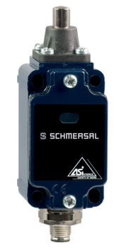
Product picture (catalogue individual photo)
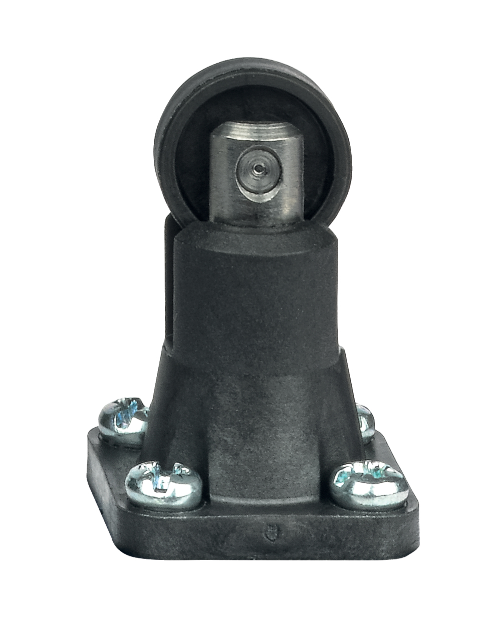
Product picture (catalogue individual photo)
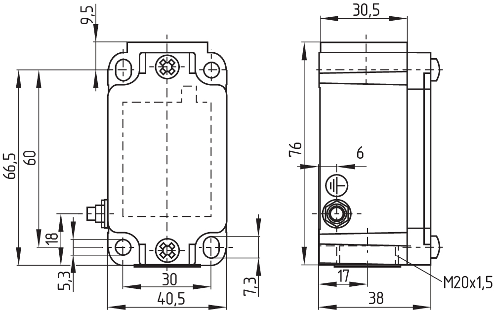
Dimensional drawing basic component
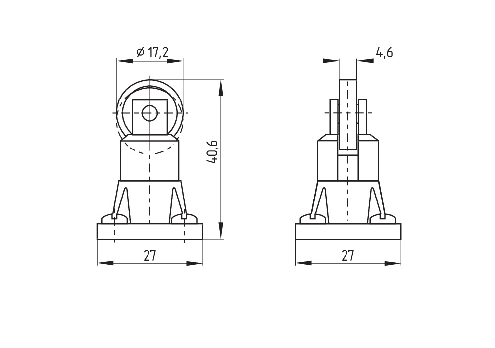
Dimensional drawing actuator
Switch travel diagram
Operating principle
Schmersal, Inc., 115 E Stevens Ave, Suite 208, Valhalla, NY 10595
The details and data referred to have been carefully checked. Images may diverge from original. Further technical data can be found in the manual. Technical amendments and errors possible.
Generated on: 9/4/2025, 8:34 AM
.png?id=e5ef4d56dad486103335c34b5b46f1ce)
