AES 1155

AES 1155
Downloads
- Monitoring of BNS range magnetic safety sensors
- 1 safety contact, STOP 0
Ordering data
| Note (Delivery capacity) |
Ikke tilgjengelig! |
| Product type description |
AES 1155 |
| Article number (order number) |
101170041 |
| EAN (European Article Number) |
4030661296968 |
| eCl@ss number, version 12.0 |
27-37-18-19 |
| eCl@ss number, version 11.0 |
27-37-18-19 |
| eCl@ss number, version 9.0 |
27-37-18-19 |
| ETIM number, version 7.0 |
EC001449 |
| ETIM number, version 6.0 |
EC001449 |
Approvals - Standards
| Certificates |
cULus |
General data
| Standards |
BG-GS-ET-14 BG-GS-ET-20 EN IEC 62061 EN ISO 13849-1 EN IEC 60947-5-1 EN IEC 60947-5-3 EN IEC 60947-5-5 EN IEC 60204-1 EN IEC 60947-1 |
| Climatic stress |
EN 60068-2-3 BG-GS-ET-14 |
| Housing material |
Plast, glassfiber forsterket termoplast, ventilert |
| Gross weight |
215 g |
General data - Features
| Wire breakage detection |
Ja |
| Cross-circuit detection |
Ja |
| Automatic reset function |
Ja |
| Reset after disconnection of supply voltage |
Ja |
| Earth connection detection |
Ja |
| Integral system diagnostics, status |
Ja |
| Number of LEDs |
1 |
| Number of normally closed (NC) |
2 |
| Number of normally open (NO) |
2 |
| Number of undelayed semi-conductor outputs with signaling function |
2 |
| Number of safety contacts |
1 |
| Safety classification |
| Standards |
EN ISO 13849-1 EN IEC 61508 |
| Stop-Category |
0 |
| Safety classification - Relay outputs |
| Performance Level, up to |
d |
| Category |
3 |
| PFH value |
1,00 x 10⁻⁷ /h |
| Notice |
Inntil maks. 50 000 omkoblingssykluser/år og ved maks. 80% kontaktbelastning |
| Safety Integrity Level (SIL), suitable for applications in |
2 |
| Mission time |
20 Year(s) |
Mechanical data
| Mechanical lifetime, minimum |
20.000.000 Operations |
| Mounting |
kneppes inn på standard DIN-skinne iht. EN 60715 |
Mechanical data - Connection technique
| Terminal designations |
IEC/EN 60947-1 |
| Cable section, minimum |
0,25 mm² |
| Cable section, maximum |
2,5 mm² |
| Tightening torque of Clips |
0,6 Nm |
| Allowed type of cable |
solid single-wire flexible |
| Terminal (mechanical) |
1000075113 |
Mechanical data - Dimensions
| Width |
22,5 mm |
| Height |
100 mm |
| Depth |
121 mm |
Ambient conditions
| Degree of protection of the enclosure |
IP40 |
| Degree of protection of the installation space |
IP54 |
| Degree of protection of clips or terminals |
IP20 |
| Ambient temperature |
+0 ... +55 °C |
| Storage and transport temperature |
-25 ... +70 °C |
| Resistance to vibrations |
10...55 Hz, Amplitude 0,35 mm, ± 15 % |
| Restistance to shock |
30 g / 11 ms |
Ambient conditions - Insulation values
| Rated impulse withstand voltage Uimp |
4 kV |
| Overvoltage category |
III |
| Degree of pollution |
2 |
Electrical data
| Frequency range |
50 Hz 60 Hz |
| Operating voltage |
24 VAC -15 % / +10 % |
| Ripple voltage |
10 % |
| Thermal test current |
6 A |
| Rated operating voltage |
24 VAC |
| Rated operating voltage |
24 VDC |
| Rated AC voltage for controls, 50 Hz, minimum |
20.4 VAC |
| Rated control voltage at AC 50 Hz, maximum |
26.4 VAC |
| Rated AC voltage for controls, 60 Hz, minimum |
20.4 VAC |
| Rated control voltage at AC 60 Hz, maximum |
26.4 VAC |
| Rated AC voltage for controls at DC minimum |
20,4 VDC |
| Rated control voltage at DC, maximum |
28,8 VDC |
| Electrical power consumption |
5 W |
| Contact resistance, maximum |
0,1 Ω |
| Note (Contact resistance) |
I ny tilstand |
| Drop-out delay in case of power failure, typically |
80 ms |
| Drop-out delay in case of emergency, typically |
20 ms |
| Pull-in delay at automatic start, maximum, typically |
100 ms |
| Pull-in delay at RESET, typically |
20 ms |
| Material of the contacts, electrical |
Ag-Ni 10 og 0,2 µm gullbelagt |
Electrical data - Safe relay outputs
| Voltage, Utilisation category AC-15 |
230 VAC |
| Current, Utilisation category AC-15 |
6 A |
| Voltage, Utilisation category DC-13 |
24 VDC |
| Current, Utilisation category DC-13 |
6 A |
| Switching capacity, minimum |
10 VDC |
| Switching capacity, minimum |
10 mA |
| Switching capacity, maximum |
250 VAC |
| Switching capacity, maximum |
8 A |
Electrical data - Digital inputs
| Input signal, HIGH Signal "1" |
10 … 30 VDC |
| Input signal, LOW Signal "0" |
0 … 2 VDC |
| Conduction resistance, maximum |
40 Ω |
Electrical data - Digital Output
| Voltage, Utilisation category DC-12 |
24 VDC |
| Current, Utilisation category DC-12 |
0,1 A |
Electrical data - Relay outputs (auxiliary contacts)
| Switching capacity, maximum |
24 VDC |
| Switching capacity, maximum |
2 A |
Electrical data - Electromagnetic compatibility (EMC)
| EMC rating |
EMC-Directive |
Integral system diagnosis (ISD)
| Note (ISD -Faults) |
Følgende feil er registrert av sikkerhetsovervåkingsmodulene og indikert av ISD. |
| Faults |
Sikkerhetsreleet vil ikke trekke inn eller falle ut Dørkontaktene vil ikke åpne eller lukke Tverrkabel- eller kortslutningsovervåking av bryterforbindelsene Brudd på bryterforbindelsene Feil på inngangskretsene eller relékontrollkretsene på sikkerhetsovervåkingsmodulen |
Other data
| Note (applications) |
Sikkerhetssensor sikkerhetsinnretning |
Note
| Note (General) |
Induktive belastninger (f.eks. kontaktorer, reléer, etc.) må undertrykkes ved hjelp av en egnet krets. |
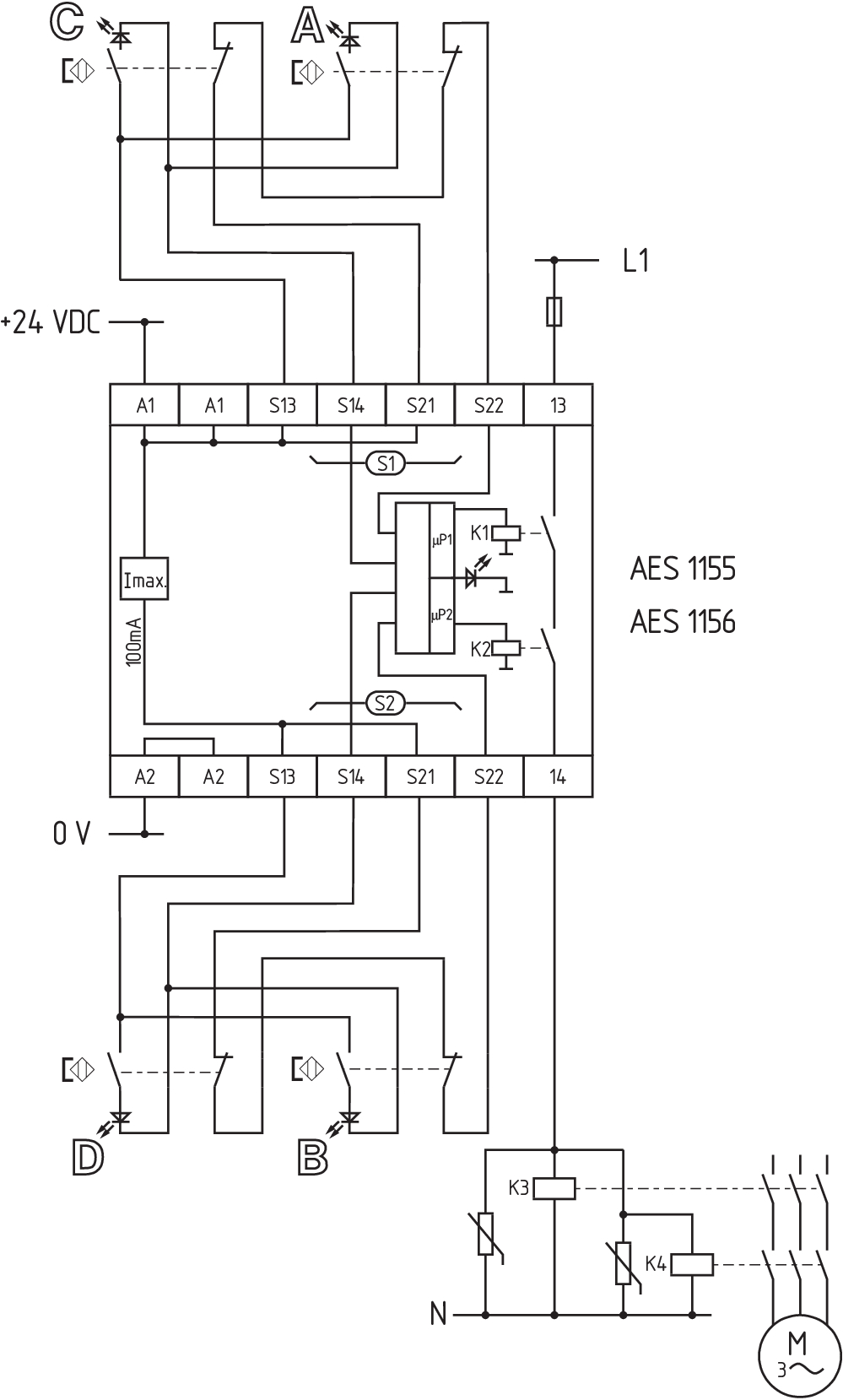
Wiring example
| Note (Wiring diagram) |
Overvåke et antall vernedører med magnetiske sikkerhetssensorer i BNS-serien Kablingsskjemaet vises med vernedørene lukket og i de-energisert tilstand. Dersom en eller to eksterne releer eller kontaktorer brukes for å bryte lasten, kan systemet bare klassifiseres i kategori 3 iht EN ISO 13849-1 dersom utelukkelse av filen "Feil på eksterne kontaktorer" kan substansieres og er dokumenter, f.eks. ved bruk av pålitelige nedgraderte kontaktorer. En andre kontaktor for økning av sikkerheten ved redundant utkobling av lasten. ISD-tabellene (Integrert System-Diagnose) for analyse av feilindikasjoner og årsakene til dem er vist i vedlegget. For å sikre en eller flere vaktdører opp til PL d og kategori 3 NC-kontakt må ha tvangsmessig bryting når vernedøren er åpnet. Utvidelse av aktiveringsforsinkelsestid: Aktiveringsforsinkelsestiden kan økes fra 0,1 s til 1 s ved å endre posisjon på en jumperlenkeforbindelse under dekselet på enheten. |
Språk filter
Datablad
Bruksanvisning og konformitetserklæring
UL sertifikat
kablingseksempel (elektr. kabling)
Last ned den nyeste versjonen av Adobe Reader
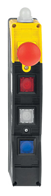
Produktbilde (enkelt katalogbilde)
kablingseksempel
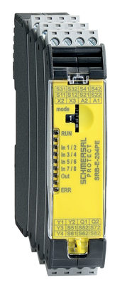
103008070 SRB-E-204PE
- Plug-in screw terminals with coding
- Input expander module
- 1 oder 2-channel control
- Monitoring of 4 sensors
- 2 Safety outputs
- 4 Signalling outputs

103009973 SRB-E-204ST
- Plug-in screw terminals with coding
- STOP 0 Function
- Monitoring of 4 sensors
- Start button / Auto-start
- 2 Safety outputs
- 4 Signalling outputs
| EU Declaration of Conformity |  |
| Original | K.A. Schmersal GmbH & Co. KG Möddinghofe 30 42279 Wuppertal Germany Internet: www.schmersal.com |
| Declaration: | We hereby certify that the hereafter described components both in their basic design and construction conform to the applicable European Directives. |
| Name of the component: | AES 1135/1136 AES 1165/1165-2250 AES 1235/1236 AES 1265/1265-2250 AES 2135 AES 2335/2365 AES 2535 |
| Type: | See ordering code |
| Description of the component: | Safety-monitoring module |
| Relevant Directives: | Machinery Directive | 2006/42/EC |
| EMC-Directive | 2014/30/EU | |
| RoHS-Directive | 2011/65/EU |
| Applied standards: | DIN EN 60947-5-1:2018 DIN EN ISO 13849-1:2016 DIN EN ISO 13849-2:2013 |
| Notified body, which approved the full quality assurance system, referred to in Appendix X, 2006/42/EC: | TÜV Rheinland Industrie Service GmbH Am Grauen Stein, 51105 Köln ID n°: 0035 |
| Person authorised for the compilation of the technical documentation: | Oliver Wacker Möddinghofe 30 42279 Wuppertal |
| Place and date of issue: | Wuppertal, January 31, 2024 |
 |
| Authorised signature Philip Schmersal Managing Director |
Schmersal India Pvt. Ltd., Plot No - G-7/1, Ranjangaon MIDC, Tal. - Shirur, Dist.- Pune 412 220
Data og verdier er kontrollert omhyggelig. Bilder kan avvike fra originalen. Ytterligere tekniske data finner du i manualen. Tekniske modifiseringer og feil kan forkomme.
Generert til 10.09.2025, 10:41
Nylig sett

Z4K 236-11ZR-1816