SRB202CS/T 24VDC
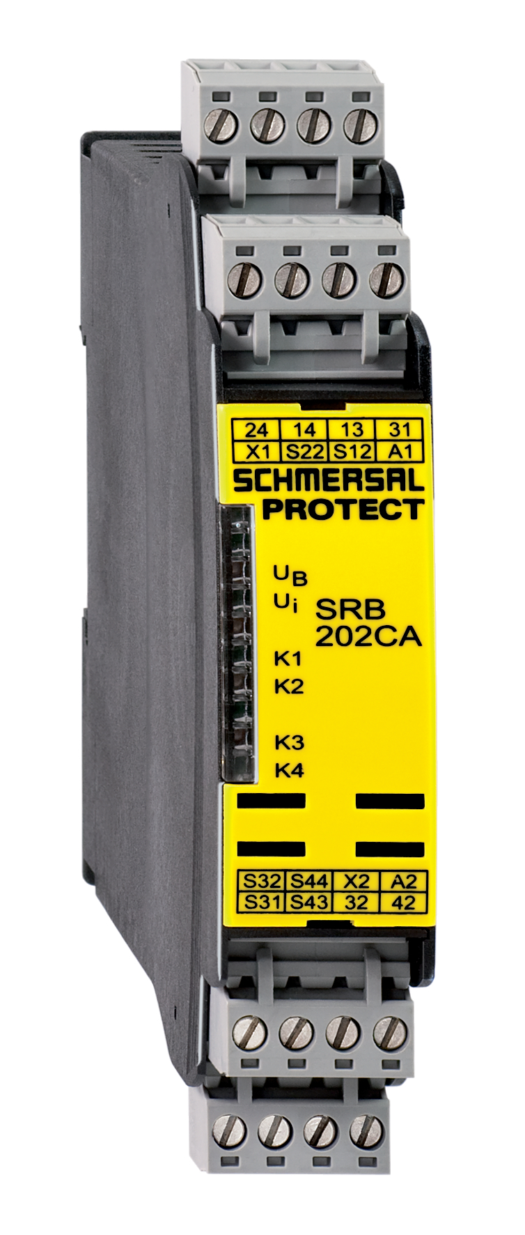
SRB202CS/T 24VDC
- Level 1: Reset with edge detection, Level 2 Opener (NC) / Opener (NC)
- Two-functions safety monitoring module (double evaluation)
- 2 enabling paths with different shut-down behaviour, e.g. emergency exit opens both enabling paths (level 1); guard door monitoring only opens the second enabling path (level 2)
- Suitable for signal processing of potential-free contacts, e.g. Emergency Stop command devices (level 1), position switches with safety function, solenoid interlocks and safety sensors (level 2)
- 2 Signalling outputs
Ordering data
| Replacement article number |
101177155 |
| Product type description |
SRB202CS/T 24VDC |
| Article number (order number) |
101176210 |
| EAN (European Article Number) |
4250116201907 |
| eCl@ss number, version 12.0 |
27-37-18-19 |
| eCl@ss number, version 11.0 |
27-37-18-19 |
| eCl@ss number, version 9.0 |
27-37-18-19 |
| ETIM number, version 7.0 |
EC001449 |
| ETIM number, version 6.0 |
EC001449 |
| Notice |
Produto descontinuado |
Approvals - Standards
| Certificates |
cULus |
General data
| Standards |
EN IEC 62061 EN ISO 13849-1 EN IEC 60947-5-1 EN IEC 60947-5-3 EN IEC 60947-5-5 EN IEC 61508 EN IEC 60204-1 EN IEC 60947-1 |
| Climatic stress |
EN 60068-2-78 |
| Housing material |
Plástico, termoplástico reforçado com fibra de vidro, auto-extinção de fogo |
| Gross weight |
235 g |
General data - Features
| Electronic Fuse |
Sim |
| Wire breakage detection |
Sim |
| Removable Terminals |
Sim |
| Start input |
Sim |
| Feedback circuit |
Sim |
| Automatic reset function |
Sim |
| Reset edge detection |
Sim |
| Earth connection detection |
Sim |
| Integral system diagnostics, status |
Sim |
| Number of auxiliary contacts |
2 |
| Number of inputs for NC |
2 |
| Number of inputs for NO |
2 |
| Number of LEDs |
6 |
| Number of safety contacts |
2 |
| Safety classification |
| Vorschriften |
EN IEC 60947-5-1 EN IEC 61508 |
| Stop-Category |
0 |
| Safety classification - Relay outputs |
| Performance Level, stop 0, up to |
e |
| Category, Stop 0 |
4 |
| Diagnostic Coverage (DC) Level, Stop 0 |
≥ 99 % |
| PFH value, Stop 0 |
2,00 x 10⁻⁸ /h |
| Safety Integrity Level (SIL), Stop 0, suitable for applications in |
3 |
| Mission time |
20 Year(s) |
| Common Cause Failure (CCF), minimum |
65 |
Mechanical data
| Mechanical lifetime, minimum |
10.000.000 Operations |
| Mounting |
Fixação rápida para perfil normalizado segundo a DIN EN 60715 |
Mechanical data - Connection technique
| Terminal designations |
IEC/EN 60947-1 |
| Cable section, minimum |
0,25 mm² |
| Cable section, maximum |
2,5 mm² |
| Tightening torque of Clips |
0,6 Nm |
| Allowed type of cable |
Rígido de um fio Flexível |
| Terminal (mechanical) |
1000075113 |
Mechanical data - Dimensions
| Width |
22,5 mm |
| Height |
100 mm |
| Depth |
121 mm |
Ambient conditions
| Degree of protection of the enclosure |
IP40 |
| Degree of protection of the installation space |
IP54 |
| Degree of protection of clips or terminals |
IP20 |
| Ambient temperature |
-25 ... +45 °C |
| Storage and transport temperature |
-40 ... +85 °C |
| Resistance to vibrations |
10 ... 55 Hz, amplitude 0,35 mm |
| Restistance to shock |
10 g / 11 ms |
Ambient conditions - Insulation values
| Rated impulse withstand voltage Uimp |
4 kV |
| Overvoltage category |
III |
| Degree of pollution |
2 |
Electrical data
| Operating voltage |
24 VDC -10 % / +20 % |
| Ripple voltage |
10 % |
| Rated operating voltage |
24 VDC |
| Rated AC voltage for controls at DC minimum |
20,4 VDC |
| Rated control voltage at DC, maximum |
28,8 VDC |
| Electrical power consumption |
4,4 W |
| Contact resistance, maximum |
0,1 Ω |
| Note (Contact resistance) |
em perfeitas condições |
| Drop-out delay in case of power failure, typically |
80 ms |
| Drop-out delay in case of emergency, typically |
20 ms |
| Pull-in delay at automatic start, maximum, typically |
100 ms |
| ON delay at automatic start |
Ajustável |
| Pull-in delay at RESET, typically |
20 ms |
| Material of the contacts, electrical |
Ag-Ni, auto limpante, contactos com guia positivo |
Electrical data - Safe relay outputs
| Voltage, Utilisation category AC-15 |
250 VAC |
| Current, Utilisation category AC-15 |
6 A |
| Voltage, Utilisation category DC-13 |
24 VDC |
| Current, Utilisation category DC-13 |
6 A |
| Switching capacity, minimum |
10 VDC |
| Switching capacity, minimum |
10 mA |
| Switching capacity, maximum |
250 VAC |
| Switching capacity, maximum |
8 A |
Electrical data - Digital inputs
| Conduction resistance, maximum |
40 Ω |
Electrical data - Relay outputs (auxiliary contacts)
| Switching capacity, maximum |
24 VDC |
| Switching capacity, maximum |
2 A |
Electrical data - Electromagnetic compatibility (EMC)
| EMC rating |
Diretiva CEM |
Status indication
| Indicated operating states |
Posição dos relés K2 Posição dos relés K1 Tensão interna de operação Uisub> Posição dos relés K3 |
Other data
| Note (applications) |
Sensor de segurança Dispositivo de segurança Botão "Paragem de Emergência" Interruptor de emergência - acionamento por cabo |
Note
| Note (General) |
Cargas indutivas (contactores, reles, etc.) deverão ser absorvidas por meio de circuitos apropriados |
| Note (Cross-circuit detection) |
Nível 1 |
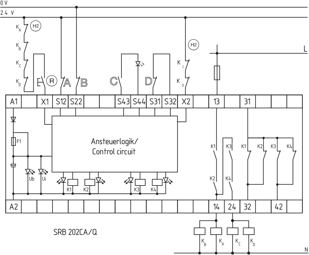
Wiring example
| Note (Wiring diagram) |
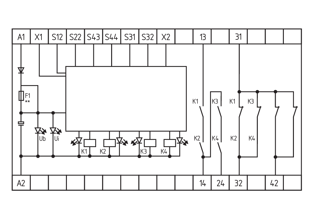
O exemplo de comutação é o do dispositivo de segurança fechado mostrando o estado sem a presença de tensão. Nível de potência: comando de dois canais, apropriado para amplificação e multiplicação de canal através de contactores ou relés com contactos forçados. O controle reconhece curto-circuitos, ruturas de cabo e aterramento dos circuitos de supervisão Nível da entrada: Controle de 2 canais, representado no exemplo de uma comutação "Paragem de Emergência" (nível 1) com botão externo de rearme (R), e uma supervisão portas (nível 2) com circuito de retorno (H2). Arranque automático (nível 1): A programação para arranque automático é executada através da interligação do circuito de retorno nos terminais X1/+24VDC. Arranque automático (nível 2): A programação de arranque automático é efetuada através da integração do circuito de retorno nos terminais X2/+24VDC. Quando o circuito de retorno não é necessário, ele pode ser substituído por uma ponte. 1 contacto NF por nível sinaliza respetivamente o estado do nível 1 e do nível 2 |
Filtro de idioma
Ficha técnica
Manual de instruções e Declaração de conformidade
Certificação UL
Exemplo de ligação (cablagem elétrica)
SISTEMA-VDMA Biblioteca/Library
Faça download da versão mais recente do Adobe Reader
Foto do produto (foto individual do catálogo )
Exemplo de ligação
Exemplo de ligação
Símbolo (norma técnica)

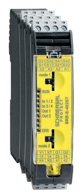
103007221 SRB-E-402ST
- Two-functions safety monitoring module (double evaluation), 2 x STOP 0
- 2 x 1 oder 2-channel control
- 2 x Start button / Auto-start
- 1 x Monitoring two-hand control panels to ISO 13851
- 2 safety contacts
- 2 Safety outputs
| EU Declaration of Conformity |  |
| Original | K.A. Schmersal GmbH & Co. KG Möddinghofe 30 42279 Wuppertal Germany Internet: www.schmersal.com |
| Declaration: | We hereby certify that the hereafter described components both in their basic design and construction conform to the applicable European Directives. |
| Name of the component: | SRB202CS / SRB202CS/T / SRB202CA / SRB202CA/T / SRB202CA/Q / SRB202CA/QT |
| Description of the component: | Safety-monitoring module for emergency stop circuits, guard door monitoring and magnetic safety switches |
| Relevant Directives: | Machinery Directive | 2006/42/EC |
| EMC-Directive | 2014/30/EU | |
| RoHS-Directive | 2011/65/EU |
| Applied standards: | EN 60947-5-1:2004 + AC:2005 + A1:2009 EN 60947-5-1:2017 EN ISO 13850:2015 EN ISO 13849-1:2015 EN ISO 13849-2:2012 EN 61326-3-1:2017 |
| Notified body, which approved the full quality assurance system, referred to in Appendix X, 2006/42/EC: | TÜV Rheinland Industrie Service GmbH Am Grauen Stein, 51105 Köln ID n°: 0035 |
| Person authorised for the compilation of the technical documentation: | Oliver Wacker Möddinghofe 30 42279 Wuppertal |
| Place and date of issue: | Wuppertal, November 22, 2021 |
 |
| Authorised signature Philip Schmersal Managing Director |
Schmersal India Pvt. Ltd., Plot No - G-7/1, Ranjangaon MIDC, Tal. - Shirur, Dist.- Pune 412 220
Os dados e informações anteriores foram verificados cuidadosamente. As imagens podem ser diferentes do original. Mais informações técnicas podem ser encontradas nos manuais de instruções. Sujeito a modificações técnicas e erros.
Gerado em 17/08/2025 16:51