AES 3075 24 VDC
AES 3075 24 VDC
- Monitoring of BNS range magnetic safety sensors
- 2 safety contacts, STOP 0
- 4 Signalling outputs
Ordering data
| Note (Delivery capacity) |
Ej tillgänglig! |
| Product type description |
AES 3075 24 VDC |
| Article number (order number) |
101138576 |
| EAN (European Article Number) |
4030661281360 |
| eCl@ss number, version 12.0 |
27-37-18-19 |
| eCl@ss number, version 11.0 |
27-37-18-19 |
| eCl@ss number, version 9.0 |
27-37-18-19 |
| ETIM number, version 7.0 |
EC001449 |
| ETIM number, version 6.0 |
EC001449 |
Approvals - Standards
| Certificates |
cULus |
General data
| Standards |
BG-GS-ET-14 BG-GS-ET-20 EN IEC 62061 EN ISO 13849-1 EN IEC 60947-5-1 EN IEC 60947-5-3 EN IEC 60947-5-5 EN IEC 60204-1 EN IEC 60947-1 |
| Housing material |
Plast, glasfiberförstärkt termoplast |
| Gross weight |
379 g |
General data - Features
| Wire breakage detection |
Ja |
| Cross-circuit detection |
Ja |
| Start input |
Ja |
| Feedback circuit |
Ja |
| Automatic reset function |
Ja |
| Integral system diagnostics, status |
Ja |
| Number of LEDs |
1 |
| Number of normally closed (NC) |
4 |
| Number of normally open (NO) |
4 |
| Number of undelayed semi-conductor outputs with signaling function |
4 |
| Number of safety contacts |
2 |
| Number of signalling outputs |
4 |
| Safety classification |
| Vorschriften |
EN ISO 13849-1 EN IEC 61508 |
| Stop-Category |
0 |
| Safety classification - Relay outputs |
| Performance Level, up to |
d |
| Category |
3 |
| PFH value |
1,00 x 10⁻⁷ /h |
| Notice |
upp till max. 50 000 funktionsväxlingar per år och vid max. 80% kontaktlast |
| Safety Integrity Level (SIL), suitable for applications in |
2 |
| Mission time |
20 Year(s) |
Mechanical data
| Mounting |
snäpps på standard-DIN-skena enligt EN 60715 |
Mechanical data - Connection technique
| Cable section, maximum |
4 mm² |
| Note |
All information i kabeldelen är inklusive kabelhylsor. |
| Tightening torque of Clips |
0,4 Nm |
| Terminal (mechanical) |
1000075113 |
Mechanical data - Dimensions
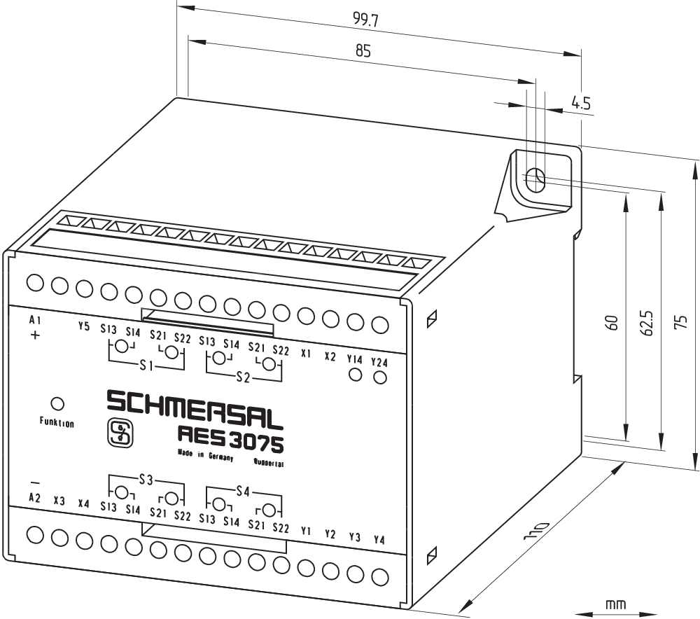
| Width |
75 mm |
| Height |
100 mm |
| Depth |
110 mm |
Ambient conditions
| Degree of protection of the enclosure |
IP40 |
| Degree of protection of the installation space |
IP54 |
| Degree of protection of clips or terminals |
IP20 |
| Ambient temperature |
+0 ... +55 °C |
| Storage and transport temperature |
-25 ... +70 °C |
| Resistance to vibrations |
10...55 Hz, Amplitud 0,35 mm, ± 15 % |
| Restistance to shock |
30 g / 11 ms |
Ambient conditions - Insulation values
| Rated impulse withstand voltage Uimp |
0,5 kV |
| Overvoltage category |
III |
| Degree of pollution |
2 |
Electrical data
| Frequency range |
50 Hz 60 Hz |
| Operating voltage |
24 VAC -15 % / +10 % |
| Ripple voltage |
10 % |
| Thermal test current |
4 A |
| Rated operating voltage |
24 VAC |
| Rated operating voltage |
24 VDC |
| Rated AC voltage for controls, 50 Hz, minimum |
20.4 VAC |
| Rated control voltage at AC 50 Hz, maximum |
26.4 VAC |
| Rated AC voltage for controls, 60 Hz, minimum |
20.4 VAC |
| Rated control voltage at AC 60 Hz, maximum |
26.4 VAC |
| Rated AC voltage for controls at DC minimum |
20,4 VDC |
| Rated control voltage at DC, maximum |
28,8 VDC |
| Electrical power consumption |
8 W |
| Contact resistance, maximum |
0,1 Ω |
| Note (Contact resistance) |
i nyskick |
| Drop-out delay in case of power failure, typically |
80 ms |
| Drop-out delay in case of emergency, typically |
20 ms |
| Pull-in delay at automatic start, maximum, typically |
100 ms |
| Pull-in delay at RESET, typically |
20 ms |
Electrical data - Safe relay outputs
| Voltage, Utilisation category AC-15 |
230 VAC |
| Current, Utilisation category AC-15 |
6 A |
| Voltage, Utilisation category DC-13 |
24 VDC |
| Current, Utilisation category DC-13 |
6 A |
| Switching capacity, minimum |
10 VDC |
| Switching capacity, minimum |
10 mA |
| Switching capacity, maximum |
250 VAC |
| Switching capacity, maximum |
8 A |
Electrical data - Digital inputs
| Input signal, HIGH Signal "1" |
10 … 30 VDC |
| Input signal, LOW Signal "0" |
0 … 2 VDC |
| Conduction resistance, maximum |
40 Ω |
Electrical data - Digital Output
| Voltage, Utilisation category DC-12 |
24 VDC |
| Current, Utilisation category DC-12 |
0,1 A |
Electrical data - Relay outputs (auxiliary contacts)
| Switching capacity, maximum |
24 VDC |
| Switching capacity, maximum |
2 A |
Electrical data - Electromagnetic compatibility (EMC)
| EMC rating |
EMC-Directive |
Integral system diagnosis (ISD)
| Note (ISD -Faults) |
Följande fel registreras av säkerhetsmodulerna och indikeras av ISD. |
| Faults |
Dörrkontakter misslyckas med att öppna eller sluta Kortslutningsövervakning av ledningarna på ingångssidan Avbrott i brytaranslutningarna Fel på ingångskretsarna till säkeretreläet |
Other data
| Note (applications) |
Säkerhetssensor Skyddsanordning |
Note
| Note (General) |
Induktiva laster (t.ex. kontaktorer, reläer etc.) måste dämpas med hjälp av en lämplig krets. |
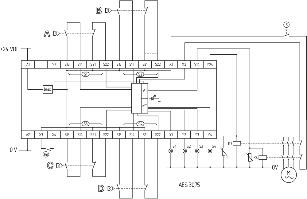
Wiring example
| Note (Wiring diagram) |
Kopplingsdiagrammet visas med skyddsdörrarna stängda och i strömlöst tillstånd. ISD-tabellerna (integrerad systemdiagnos) för analys av felindikationerna och deras orsaker visas i bilagan. Startknapp (S): En startknapp (slutande kontakt) kan bindas in i returkretsen som tillval. När skyddsanordningen är stängd stängs säkerhetskontakterna först efter att startknappen aktiverats. Returkretsen övervakar positionen för de tvångsstyrda brytande kontakterna för kontaktor K3 och K4. Till låsning av 4 skyddsdörrar upp till PL d och kategori 3 Övervakar 4 skyddsdörr(ar), var och en med en magnetbrytare för säkerhet i serie BNS De externa kontaktorernas br kontakter måste seriekopplas till X1 (+) och X2. Om mindre än 4 brytare ansluts måste klämma S21/S22 som inte används bryggas för anslutning av en brytande kontakt. Detta gäller för jumperpositionen i säkerhetsreläet med konfigurationen brytande kontakt/slutande kontakt. Brytaren (H6) som är ansluten till terminal X3 och X4 kopplar till och från aktiveringsutgångarna Y14 och Y24 med skyddsdörren stängd. Om ingen brytare är ansluten måste en bygling göras mellan terminalerna X3 och X4. |
Språk filter
Datablad
Driftsinstruktion och EU-försäkran om överensstämmelse
UL-certifikat
Kopplingsexempel (elektr. trådning)
Kraft-Väg diagram
SISTEMA-VDMA Bibliotek/Library
Ladda ned senaste versionen av Adobe reader
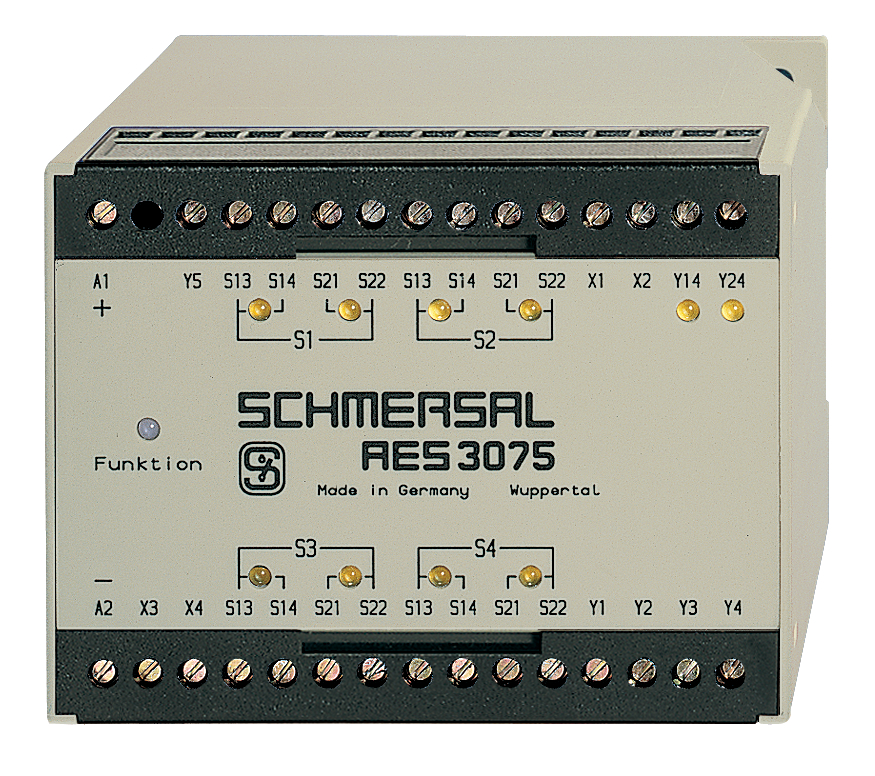
Produktbild (singelfoto i katalog)
Måttritning (grundkomponent)
Kopplingsexempel

103009973 SRB-E-204ST
- Plug-in screw terminals with coding
- STOP 0 Function
- Monitoring of 4 sensors
- Start button / Auto-start
- 2 Safety outputs
- 4 Signalling outputs
| EU Declaration of Conformity |  |
| Original | K.A. Schmersal GmbH & Co. KG Möddinghofe 30 42279 Wuppertal Germany Internet: www.schmersal.com |
| Declaration: | We hereby certify that the hereafter described components both in their basic design and construction conform to the applicable European Directives. |
| Name of the component: | AES 3075 |
| Type: | See ordering code |
| Description of the component: | Safety-monitoring module for non-contact safety switches and safety relay combination in connection with the BNS series magnetic safety switches |
| Relevant Directives: | Machinery Directive | 2006/42/EC |
| EMC-Directive | 2014/30/EU | |
| RoHS-Directive | 2011/65/EU |
| Applied standards: | DIN EN 60947-5-3:2014, DIN EN ISO 13849-1:2016, DIN EN ISO 13849-2:2013 |
| Notified body for Type Examination: | DGUV Test Prüf- und Zertifizierungsstelle Fachbereich Elektrotechnik Gustav-Heinemann-Ufer 130 50968 Köln ID n°: 0340 |
| EU-Type Examination Certificate: | ET 16122 |
| Person authorised for the compilation of the technical documentation: | Oliver Wacker Möddinghofe 30 42279 Wuppertal |
| Place and date of issue: | Wuppertal, November 10, 2017 |
 |
| Authorised signature Philip Schmersal Managing Director |
Schmersal India Pvt. Ltd., Plot No - G-7/1, Ranjangaon MIDC, Tal. - Shirur, Dist.- Pune 412 220
Alla data och värden har kontrollerats noga. Bilder kan avvika från originalet. Ytterligare tekniska data finns i manualen. Tekniska ändringar och fel förbehålles.
Genererat den 2025-08-23 00:38