BN 325-RG-1279

BN 325-RG-1279
Downloads
| Product type description: BN 325-R(1)-(2) |
| (1) | |
| without LED | |
| G | with LED |
| (2) | |
| Blade terminal 4,8 mm and 1 shielding plate | |
| 1239 | Blade terminal 4,8 mm and 2 shielding plate |
| 1389 | Blade terminal 6,3 mm and 2 shielding plates |
| 1279 ..M | Cable (Length in m) on the left side and 2 shielding plates |
| 1279-2 ..M | Cable (Length in m) on the right side and 2 shielding plates |
| LST-1279 ..M | Cable with connector M12 on the left side, Length in m |
| LST-1279-2 ..M | Cable with connector M12 on the right side, Length in m |
- Cable output left and 2 shielding plates
- Actuation from front
- Non-contact principle
- 1 Reed contakts
- Long life
- Actuating surface and direction of actuation marked by switch symbol
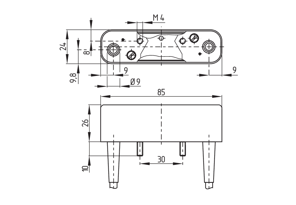
- 85 mm x 26 mm x 24 mm
- Thermoplastic enclosure
- Spade connector
Ordering data
| Product type description |
BN 325-RG-1279 |
| Article number (order number) |
101147106 |
| EAN (European Article Number) |
4030661141442 |
| eCl@ss number, version 12.0 |
27-27-43-02 |
| eCl@ss number, version 11.0 |
27-27-01-05 |
| eCl@ss number, version 9.0 |
27-27-01-05 |
| ETIM number, version 7.0 |
EC002544 |
| ETIM number, version 6.0 |
EC002544 |
General data
| Working principle |
Styrning av magnetlås |
| Housing construction form |
Block |
| Housing material |
Plast, glasfiberförstärkt termoplast |
| Gross weight |
93 g |
| Note |
Integrated shielding plate (top and bottom) |
General data - Features
| Latching |
Ja |
| Suitable for elevators |
Ja |
| Integral system diagnostics, status |
Ja |
| Cable sleeve |
Ja |
| Number of snap-in contacts |
1 |
Mechanical data
| Active area |
frontsida |
| Actuating element |
Magnetspole |
| Mechanical lifetime, minimum |
1.000.000.000 Operations |
| Actuation direction |
Lengthwise |
| Actuating speed, maximum |
18 m/s |
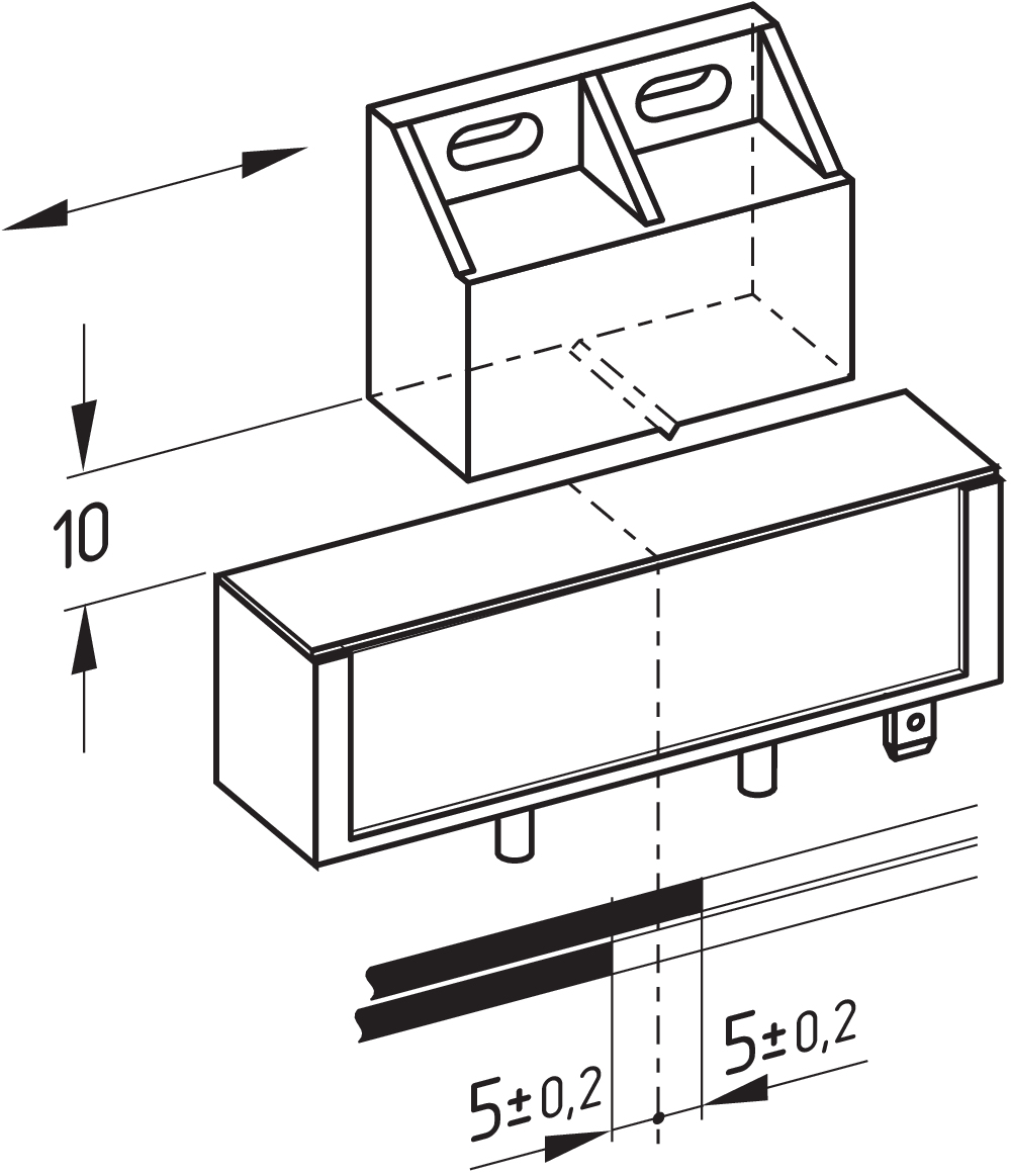
| Mounting |
baksida med 2 gängbultar |
Mechanical data - Switching distances
| Switching distance Sn |
5 mm … 55 mm 2 x BP 21S = 20 ... 55 mm BP 34S = 10 ... 25 mm BP 10N = 10 mm BP 10S = 10 mm 2 x BP 10N = 15 mm 2 x BP 10S = 15 mm BP 15N = 12 mm BP 15S = 12 mm 2 x BP 15/2N = 17 mm 2 x BP 15/2S = 17 mm BP 34N = 10 ... 25mm BP 20N = 5 ... 20 mm BP 20S = 5 ... 20 mm BP 31N = 5 ... 20 mm BP 31S = 5 ... 20 mm BP 11N = 10 mm BP 11S = 10 mm 2 x BP 11N = 20 mm 2 x BP 11S = 20 mm BP 12N = 15 mm BP 12S = 15 mm 2 x BP 12N = 10 ... 25 mm 2 x BP 12S = 10 ... 25 mm BP 21N = 15 ... 40 mm BP 21S = 15 ... 40 mm 2 x BP 21N = 20 ... 55 mm |
| Note (Switching distance Sn) |
Aktiveringsavstånd upp till 55 mm beroende aktiveringsmagnet och version |
| Note (switching distance) |
All switching distances in accordance EN IEC 60947-5-2 |
| Repeat accuracy R |
0,3 mm |
Mechanical data - Connection technique
| Length of cable |
1 m |
| Cable entry |
back, right |
| Termination |
Anslutningskabel |
| Number of cable wires |
3 |
| Wire cross-section |
0,34 mm2 |
| Wire cross-section |
22 AWG |
| Material of the Cable mantle |
PVC |
| Cable type |
LiYY |
Mechanical data - Dimensions
| Length of sensor |
24 mm |
| Width of sensor |
85 mm |
| Height of sensor |
26 mm |
Ambient conditions
| Degree of protection |
IP67 |
| Ambient temperature |
-25 ... +70 °C |
| Resistance to vibrations |
10 … 55 Hz, Amplitud 1 mm |
| Restistance to shock |
50 g / 11 ms |
| Resistant to vibration |
30 g, vid en sinusformad oscillering |
Electrical data
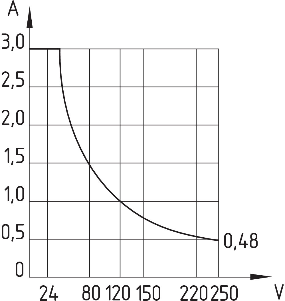
| Switching voltage, maximum |
250 VAC |
|
| Switching current, maximum |
3 A |
|
| Switching capacity, maximum |
120 VA |
|
| Switching principle |
|
|
| Bounce duration, minimum |
0,3 ms |
|
| Bounce duration, maximum |
0,6 ms |
|
| Switching frequency, maximum |
300 Hz |
|
| Maximale Schalthäufigkeit |
1.080.000 /h |
|
| Maximum switching time close (NO) |
1,5 ms |
|
| Maximum switching time open (NC) |
0,5 ms |
Scope of delivery
| Scope of delivery |
Actuator must be ordered separately. |
Accessory
| Recommendation (actuator) |
BP 10 S 2x BP 10 S BP 15 S BP 34 S BP 20 S BP 31 S BP 11 S 2x BP 11 S BP 12 S BP 21 S 2x BP 21 S BP 10 N 2x BP 10 N BP 15 N 2 x BP 15/2 N 2x BP 15/2 S BP 34 N BP 20 N BP 31 N |
| Recommendation (actuator, lift switchgear) |
BP 10 2 x BP 15/2 2 x BP 10 BP 15 BP 34 |
Note
| Note (General) |
Den brytande eller slutande funktionen beror på aktiveringsriktningen och aktiveringsmagnetens polariteten. |
Språk filter
Datablad
Driftsinstruktion och EU-försäkran om överensstämmelse
EU-försäkran om överensstämmelse
Info
Ladda ned senaste versionen av Adobe reader
Produktbild (singelfoto i katalog)
Måttritning (grundkomponent)
Kontaktdiagram
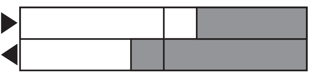
Kontaktdiagram

Diagram
Karakteristisk kurva

Karakteristisk kurva
101057534 BP 21 S
- -metal housing
- S-pole marked red
- Suitable for mounting on ferrous material
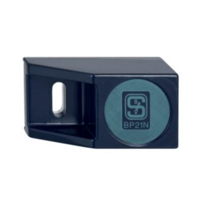
101057536 BP 21 N
- -metal housing
- N-pole marked green
- Suitable for mounting on ferrous material
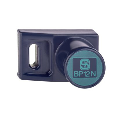
101059917 BP 12 N
- -metal housing
- N-pole marked green
- Suitable for mounting on ferrous material
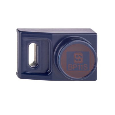
101057533 BP 11 S
- -metal housing
- S-pole marked red
- Suitable for mounting on ferrous material

101059923 BP 11 N
- -metal housing
- N-pole marked green
- Suitable for mounting on ferrous material
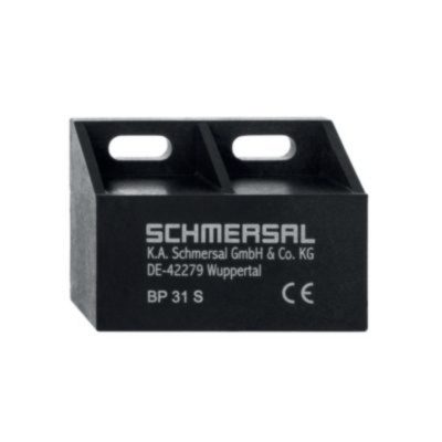
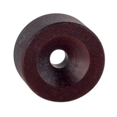
101057521 BP 31 S
- thermoplastic enclosure
- S-pole marked red
- Suitable for mounting on ferrous material with a distance of 20 mm
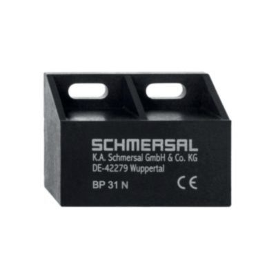
101057520 BP 31 N
- thermoplastic enclosure
- N-pole marked green
- Suitable for mounting on ferrous material with a distance of 20 mm
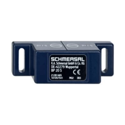
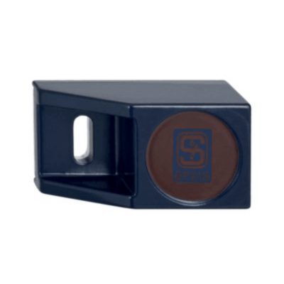
101057541 BP 20 S
- -metal housing
- S-pole marked red
- Suitable for mounting on ferrous material with a distance of 20 mm
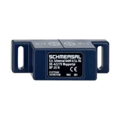
101057538 BP 20 N
- -metal housing
- N-pole marked green
- Suitable for mounting on ferrous material with a distance of 20 mm
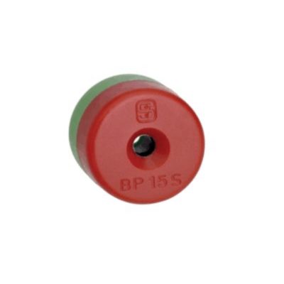
101060163 BP 15
- thermoplastic enclosure
- N-pole marked green
- S-pole marked red
- Suitable for mounting on ferrous material with a distance of 18 mm
101057531 BP 10
- Unenclosed
- Colour coding of poles by lables
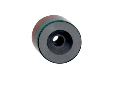
101060165 BP 15/2
- Unenclosed
- Polarity stamped in
- Suitable for mounting on ferrous material with a distance of 18 mm
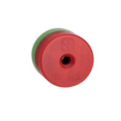
151057553 BP34
- thermoplastic enclosure
- S-pole marked red
- N-pole marked green
- Suitable for mounting on ferrous material with a distance of 25 mm
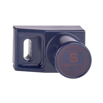
101057532 BP 12 S
- -metal housing
- S-pole marked red
- Suitable for mounting on ferrous material
Schmersal India Pvt. Ltd., Plot No - G-7/1, Ranjangaon MIDC, Tal. - Shirur, Dist.- Pune 412 220
Alla data och värden har kontrollerats noga. Bilder kan avvika från originalet. Ytterligare tekniska data finns i manualen. Tekniska ändringar och fel förbehålles.
Genererat den 2025-09-06 15:19