SRB308IT-24VAC/DC

SRB308IT-24VAC/DC
Downloads
- Level 1: Reset without edge detection, Optional Automatic reset function, Short-circuit recognition, Level 2: / Opener (NC) Normally open contact (NO)
- Multifunctional safety relay module for superior diagnostics and visualisation
- Suitable for the signal processing of outputs with contact sensors
- Suitable for signal processing of outputs connected to potentials (AOPDs), e.g. safety light grids/curtains
- Suitable for the signal processing of outputs with contact sensors
- 3 safety contacts, STOP 0
- 2 + 6 Signalling outputs
Ordering data
| Note (Delivery capacity) |
Elde mevcut değil! |
| Replacement article number |
101159511 |
| Product type description |
SRB308IT-24VAC/DC |
| Article number (order number) |
101158200 |
| EAN (European Article Number) |
4250116201556 |
| eCl@ss number, version 12.0 |
27-37-18-19 |
| eCl@ss number, version 11.0 |
27-37-18-19 |
| eCl@ss number, version 9.0 |
27-37-18-19 |
| ETIM number, version 7.0 |
EC001449 |
| ETIM number, version 6.0 |
EC001449 |
Approvals - Standards
| Certificates |
cULus |
General data
| Standards |
EN IEC 62061 EN ISO 13849-1 EN IEC 60947-5-1 EN IEC 60947-5-3 EN IEC 60947-5-5 EN IEC 61508 EN IEC 60204-1 EN IEC 60947-1 |
| Climatic stress |
EN 60068-2-78 |
| Housing material |
Plastik, fiber cam takviyeli termoplastik, havalandırılmış |
| Gross weight |
480 g |
General data - Features
| Electronic Fuse |
Evet |
| Wire breakage detection |
Evet |
| Cross-circuit detection |
Evet |
| Removable Terminals |
Evet |
| Start input |
Evet |
| Feedback circuit |
Evet |
| Automatic reset function |
Evet |
| Reset edge detection |
Evet |
| Earth connection detection |
Evet |
| Integral system diagnostics, status |
Evet |
| Number of auxiliary contacts |
2 |
| Number of LEDs |
5 |
| Number of normally closed (NC) |
2 |
| Number of undelayed semi-conductor outputs with signaling function |
6 |
| Number of safety contacts |
3 |
| Number of signalling outputs |
6 |
| Safety classification |
| Vorschriften |
EN IEC 60947-5-1 EN IEC 61508 |
| Mission time |
20 Year(s) |
| Common Cause Failure (CCF), minimum |
65 |
| Stop-Category |
0 |
| Safety classification - Relay outputs |
| Performance Level, stop 0, up to |
e |
| Category, Stop 0 |
4 |
| Diagnostic Coverage (DC) Level, Stop 0 |
≥ 99 % |
| PFH value, Stop 0 |
2,00 x 10⁻⁸ /h |
| Safety Integrity Level (SIL), Stop 0, suitable for applications in |
3 |
Mechanical data
| Mechanical life, minimum |
10.000.000 Operations |
| Mounting |
EN 60715 e uygun standart DIN rayının üzerine kilitlenir |
Mechanical data - Connection technique
| Terminal designations |
IEC/EN 60947-1 |
| Termination |
Sabit ya da esnek Vida bağlantısı M20 x 1.5 |
| Cable section, minimum |
0,25 mm² |
| Cable section, maximum |
2,5 mm² |
| Tightening torque of Clips |
0,6 Nm |
Mechanical data - Dimensions
| Width |
45 mm |
| Height |
100 mm |
| Depth |
121 mm |
Ambient conditions
| Degree of protection of the enclosure |
IP40 |
| Degree of protection of the mounting space |
IP54 |
| Degree of protection of clips or terminals |
IP20 |
| Ambient temperature |
-25 ... +45 °C |
| Storage and transport temperature |
-40 ... +85 °C |
| Resistance to vibrations |
10 ... 55 Hz, Genlik 0.35 mm |
| Restistance to shock |
30 g / 11 ms |
Ambient conditions - Insulation values
| Rated impulse withstand voltage Uimp |
4 kV |
| Overvoltage category |
III |
| Degree of pollution |
2 |
Electrical data
| Frequency range |
50 Hz 60 Hz |
| Operating voltage |
24 VAC -15 % / +10 % |
| Ripple voltage |
10 % |
| Rated operating voltage |
24 VAC |
| Rated operating voltage |
24 VDC |
| Operating current |
125 mA |
| Rated AC voltage for controls, 50 Hz, minimum |
20,4 VAC |
| Rated control voltage at AC 50 Hz, maximum |
26,4 VAC |
| Rated AC voltage for controls, 60 Hz, minimum |
20,4 VAC |
| Rated control voltage at AC 60 Hz, maximum |
26,4 VAC |
| Rated AC voltage for controls at DC minimum |
20,4 VDC |
| Rated control voltage at DC, maximum |
28,8 VDC |
| Utilisation category AC-15 |
230 VAC |
| Utilisation category AC-15 |
1,5 A |
| Utilisation category DC-13 |
24 VDC |
| Utilisation category DC-13 |
1,2 A |
| Electrical power consumption |
3 W |
| Electrical power consumption |
3 VA |
| Contact resistance, maximum |
0,1 Ω |
| Note (Contact resistance) |
yeni durumda |
| Drop-out delay in case of "emergency stop", maximum |
15 ms |
| Pull-in delay at automatic start, maximum, typically |
60 ms |
| Pull-in delay at RESET, typically |
200 ms |
| Material of the contacts, electrical |
AgSn0, Ag-Ni, kendi kendini temizler, pozitif hareket |
Electrical data - Digital inputs
| Conduction resistance, maximum |
40 Ω |
Electrical data - Electromagnetic compatibility (EMC)
| EMC rating |
EMC-Directive |
Status indication
| Indicated operating states |
Konum rölesi K2 Konum rölesi K1 Dahili çalışma gerilimi Ui Konum rölesi K3 |
Other data
| Note (applications) |
Koruma sistemi Acil Stop butonu Halatlı acil stop anahtarları Işıklı güvenlik perdesi |
Note
| Note (General) |
Inductive loads (e.g. contactors, relays, etc.) are to be suppressed by means of a suitable circuit. |
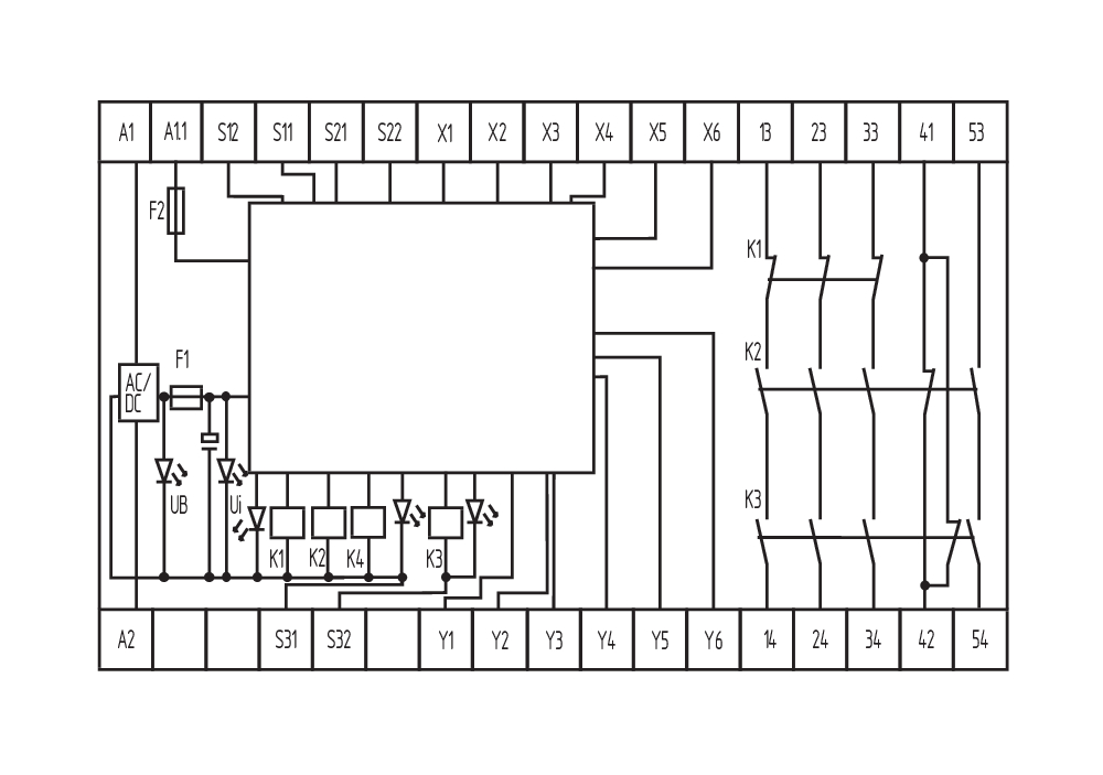
Wiring example
| Note (Wiring diagram) |
The wiring diagram is shown with guard doors closed and in de-energised condition. The ISD tables (Intergral System Diagnostics) for analysis of the fault indications and their causes are shown in the appendix. Relay outputs: Suitable for 2 channel control, for increase in capacity or number of contacts by means of contactors or relays with positive-guided contacts. The control recognises cross-short, cable break and earth leakages in the monitoring circuit. Connect potential p-type outputs of safety light grids/curtains to S12/S22. The devices must have the same reference potential. 2 channel control shown for a guard-door monitor with two contacts, of which at least one contact has positive break, with external reset button (R) and feedback circuit (H2). (example without cross-wire monitoring) For 2-channel control with cross-wire monitoring, connect the NC contact to S11/S12 and S31/S32 and bridge S21/S22 For 1-channel control, connect NC contact to S11/S12 and bridge S21/S22 and S31/S32 "Start function / Reset button: The function "trailing edge" is programmed by means of the "AF" switch located underneath the housing cover (switch position = 1). The automatic start is programmed by bridging terminals X3/X5 and by switching the "AF" switch to 0. The time offset between the channels is approx. 100 ms. An endless time offset between the channels 1 and 2 is programmed by bridging the terminals X3/X6." F1 = hibrid sigorta F2 = Çıkışlara sinyal sağlamak için sigorta |
Dil filtresi
Veri sayfası
Çalışma Talimatları ile Uygunluk beyanı
UL Sertifikası
Kablo döşeme örneği (elektr. kablolama)
Kuvvet-hareket şeması
Adobe Reader’ın son sürümünü indirin
Ürün resmi (katalog özel fotoğraf)
Kablo döşeme örneği
Kablo döşeme örneği

Kablo döşeme örneği

Sembol (teknik standart)


103007672 SRB-E-301ST
- Plug-in screw terminals with coding
- STOP 0 Function
- 1 oder 2-channel control
- Start button / Auto-start
- 1 Auxiliary contact
- 3 safety contacts
Schmersal India Pvt. Ltd., Plot No - G-7/1, Ranjangaon MIDC, Tal. - Shirur, Dist.- Pune 412 220
Veriler ve ayrıntılar dikkatli bir şekilde kontrol edilmişlerdir. Görüntüler orijinalden farklı olabilir. Daha fazla teknik veri kılavuzda bulunabilir. Teknik değişiklikler ve hatalar olabilir.
Udarbejdet d. 28.04.2025 17:43
