SRB219IT-24VAC/DC
SRB219IT-24VAC/DC
下载
- Multifunctional safety relay module for superior diagnostics and visualisation
- Suitable for the signal processing of outputs with contact sensors
- Suitable for the signal processing of outputs with contact sensors
- Suitable for signal processing of outputs connected to potentials (AOPDs), e.g. safety light grids/curtains
- 1 + 8 Signalling outputs
- 2 safety contacts, STOP 0;
1 safety contact, STOP 1 (adjustable 1 … 30 s)
Ordering data
| Note (Delivery capacity) |
不支持! |
| Replacement article number |
101159512 |
| Product type description |
SRB219IT-24VAC/DC |
| Article number (order number) |
101158208 |
| EAN (European Article Number) |
4250116201570 |
| eCl@ss number, version 12.0 |
27-37-18-19 |
| eCl@ss number, version 11.0 |
27-37-18-19 |
| eCl@ss number, version 9.0 |
27-37-18-19 |
| ETIM number, version 7.0 |
EC001449 |
| ETIM number, version 6.0 |
EC001449 |
Approvals - Standards
| Certificates |
cULus |
General data
| Standards |
EN IEC 62061 EN ISO 13849-1 EN IEC 60947-5-1 EN IEC 60947-5-3 EN IEC 60947-5-5 EN IEC 61508 EN IEC 60204-1 EN IEC 60947-1 |
| Climatic stress |
EN 60068-2-78 |
| Housing material |
玻璃纤维加固热塑塑料,带通风 |
| Gross weight |
360 g |
General data - Features
| Electronic Fuse |
是 |
| Wire breakage detection |
是 |
| Cross-circuit detection |
是 |
| Removable Terminals |
是 |
| Start input |
是 |
| Feedback circuit |
是 |
| Automatic reset function |
是 |
| Reset edge detection |
是 |
| Earth connection detection |
是 |
| Integral system diagnostics, status |
是 |
| Number of auxiliary contacts |
1 |
| Number of LEDs |
7 |
| Number of normally closed (NC) |
2 |
| Number of undelayed semi-conductor outputs with signaling function |
7 |
| Number of delayed semi-conductor outputs with signaling function. |
1 |
| Number of safety contacts |
3 |
| Number of signalling outputs |
8 |
| Safety classification |
| Vorschriften |
EN IEC 60947-5-1 EN IEC 61508 |
| Stop-Category |
0 1 |
| Safety classification - Relay outputs |
| Performance Level, stop 0, up to |
e |
| Performance Level, stop 1, up to |
d |
| Category, Stop 0 |
4 |
| Category, Stop 1 |
3 |
| Diagnostic Coverage (DC) Level, Stop 0 |
≥ 99 % |
| Diagnostic Coverage (DC) Level, Stop 1 |
> 60 % |
| PFH value, Stop 0 |
2.00 x 10⁻⁸ /h |
| PFH value, Stop 1 |
2.00 x 10⁻⁷ /h |
| Safety Integrity Level (SIL), Stop 0, suitable for applications in |
3 |
| Safety Integrity Level (SIL), Stop 1, suitable for applications in |
2 |
| Mission time |
20 Year(s) |
| Common Cause Failure (CCF), minimum |
65 |
Mechanical data
| Mechanical lifetime, minimum |
10,000,000 Operations |
| Mounting |
DIN导轨快速安装,依据EN 60715 |
Mechanical data - Connection technique
| Terminal designations |
IEC/EN 60947-1 |
| Cable section, minimum |
.25 mm² |
| Cable section, maximum |
2.5 mm² |
| Tightening torque of Clips |
0.6 Nm |
| Allowed type of cable |
实心单线 可调 |
| Terminal (mechanical) |
1000075113 |
Mechanical data - Dimensions
| Width |
45 mm |
| Height |
100 mm |
| Depth |
121 mm |
Ambient conditions
| Degree of protection of the enclosure |
IP40 |
| Degree of protection of the installation space |
IP54 |
| Degree of protection of clips or terminals |
IP20 |
| Ambient temperature |
-25 ... +45 °C |
| Storage and transport temperature |
-40 ... +85 °C |
| Resistance to vibrations |
10 ... 55 Hz,振幅 .35 mm,± 15 % |
| Restistance to shock |
30 g / 11 ms |
Ambient conditions - Insulation values
| Rated impulse withstand voltage Uimp |
4 kV |
| Overvoltage category |
III |
| Degree of pollution |
2 |
Electrical data
| Frequency range |
50 Hz 60 Hz |
| Operating voltage |
24 VAC -15 % / +10 % |
| Ripple voltage |
10 % |
| Rated operating voltage |
24 VAC |
| Rated operating voltage |
24 VDC |
| Operating current |
200 mA |
| Rated AC voltage for controls, 50 Hz, minimum |
20.4 VAC |
| Rated control voltage at AC 50 Hz, maximum |
26.4 VAC |
| Rated AC voltage for controls, 60 Hz, minimum |
20.4 VAC |
| Rated control voltage at AC 60 Hz, maximum |
26.4 VAC |
| Rated AC voltage for controls at DC minimum |
20.4 VDC |
| Rated control voltage at DC, maximum |
28.8 VDC |
| Electrical power consumption |
4.4 W |
| Electrical power consumption |
5.2 VA |
| Contact resistance, maximum |
0.1 Ω |
| Note (Contact resistance) |
处于全新的状态 |
| Drop-out delay in case of "emergency stop", maximum |
15 ms |
| Pull-in delay at automatic start, maximum, typically |
60 ms |
| Pull-in delay at RESET, typically |
200 ms |
| Material of the contacts, electrical |
氧化锡银,自清洁,强制定位 |
Electrical data - Digital inputs
| Conduction resistance, maximum |
40 Ω |
Electrical data - Electromagnetic compatibility (EMC)
| EMC rating |
EMC指令 |
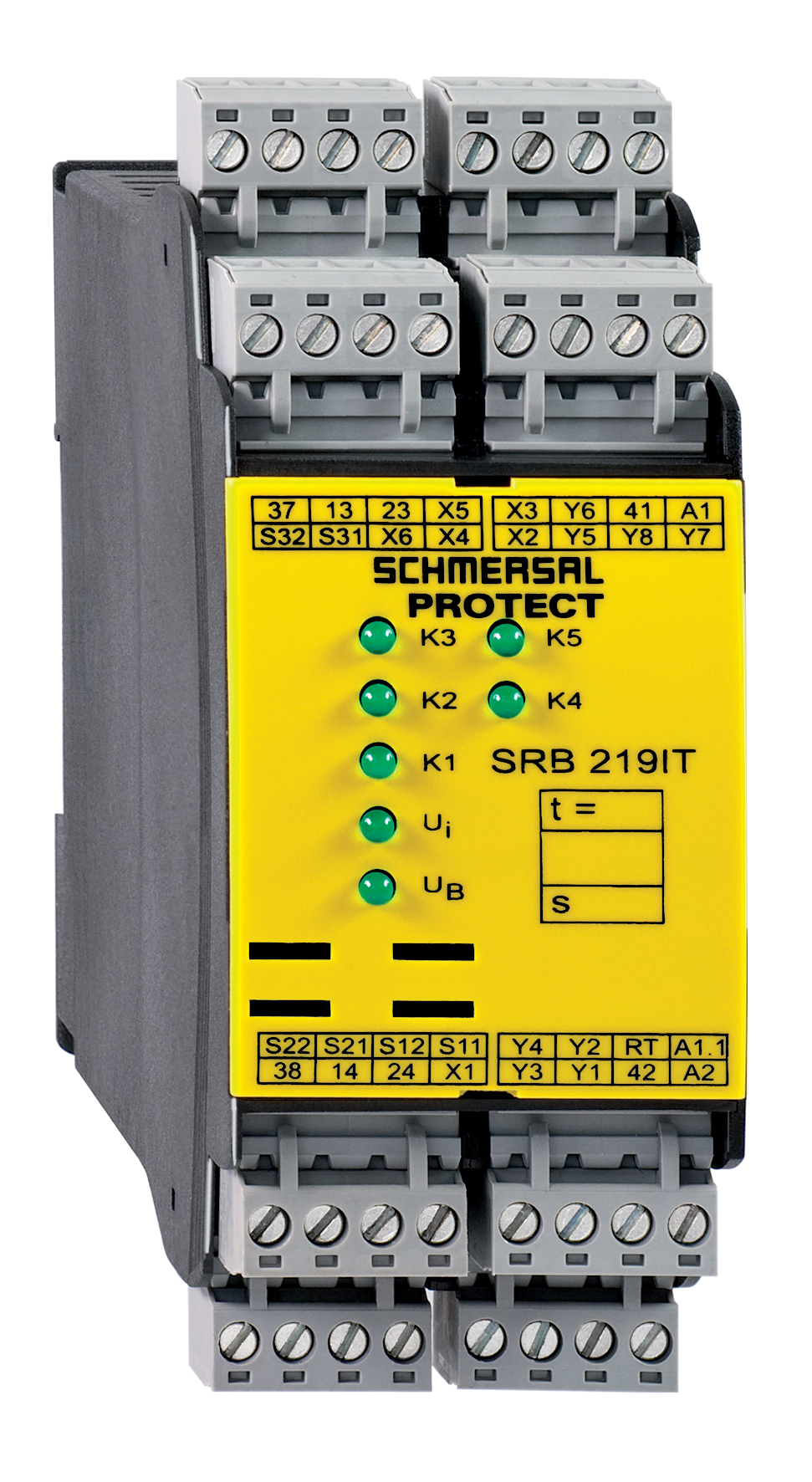
Status indication
| Indicated operating states |
位置继电器 K2 位置继电器 K1 内部工作电压 Ui 位置继电器 K3 位置继电器 K5 |
Other data
| Note (applications) |
安全传感器 防护系统 紧急停止按钮 紧急停止拉绳开关 安全光幕 |
Note
| Note (General) |
感应负载(例如接触器、继电器等)必须通过适当的电路抑制。 |
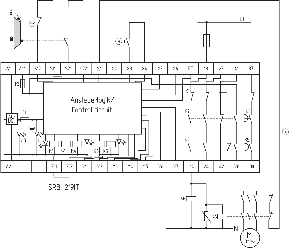
Wiring example
| Note (Wiring diagram) |
接线图显示的是防护门关闭且处于断电状态的情况。 用于分析故障指示及其原因的ISD表(综合系统诊断)如附录所示。 控制系统识别监控回路中的断线和接地故障。 继电器输出:适用于双通道控制,用于增强触点容量或增加触点数量,通过使用接触器或带强制定位触点的继电器。 将安全光栅/光幕的P型输出连接到S12/S22。设备必须具有相同的参考电位。 延时:延时安全37/38可调节1至30秒的退出延时(见设置说明)。 断开延迟时间的设置可以通过从外壳前的电位计进行。 对于带交叉监控的双通道控制,连接NC触点至S11/S12和S31/S32 并桥接S12/S22 启动功能/复位按钮:“后缘”功能是通过位于外壳下的“AF”开关来编程的(开关位置=1)。自动启动程序通过桥接端子X3/X5并将“AF”开关切换到0进行编程。通道之间的时间偏移约为100 ms。通道1和2之间的无限时间偏移通过桥接端子X3/X6进行编程。” 输入电平:该示例显示了带有两个限位开关的防护门监控的双通道控制,其中一个限位开关具有肯定断开、外部重置按钮(R)和反馈电路(H2)。(不带交叉短路监控的示例) 对于单通道控制,连接NC触点至S11/S12 并桥接S21/S22 + S31/S32 延时提前断开:退出延迟时间可以通过输入RT提前结束。输入RT可以在设定时间过去之前“关闭”延时启用电路37/38。 F1 = 混合保险丝 F2 = 信号输出保险丝 |
语言条件
数据表
操作指南及符合性声明
接线图示(电线)
下载最新版本的Adobe Reader
产品图片(单独目录照片)
接线图示
符号(技术标准)

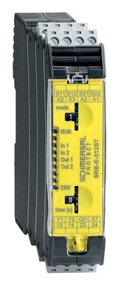
103007222 SRB-E-212ST
- Plug-in screw terminals with coding
- STOP 0 / 1 Function
- 1 oder 2-channel control
- 2 safety contacts STOP 0
- 1 Safety output STOP 1
- Drop-out delay 0 … 30
Schmersal India Pvt. Ltd., Plot No - G-7/1, Ranjangaon MIDC, Tal. - Shirur, Dist.- Pune 412 220
所涉及的详细信息和数据已经过仔细检查。 图像可能与原始图像有所不同。 您可在说明书中进一步获得技术数据。 可能会有技术修改和错误。
生成日期 2025/9/3 上午4:56
最近浏览