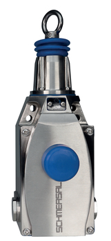
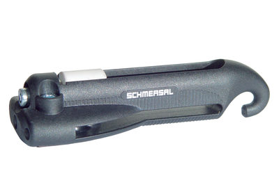
ZQ901-11
ZQ901-11
- Stainless steel enclosure
- one-side operation / wire up to 75 m long
- Release push button
- Position indicator
- Robust design
- Large wiring compartment
- Twisting of towing eye not possible
- External watertight collar
- wire pull and breakage detection
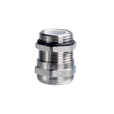
- 3 cable entries M 20 x 1.5
Ordering data
| Product type description |
ZQ901-11 |
| Article number (order number) |
137000450 |
| EAN (European Article Number) |
8905236108228 |
| eCl@ss number, version 12.0 |
27-37-12-01 |
| eCl@ss number, version 11.0 |
27-37-12-01 |
| eCl@ss number, version 9.0 |
27-37-12-01 |
| ETIM number, version 7.0 |
EC002033 |
| ETIM number, version 6.0 |
EC002033 |
Approvals - Standards
| Certificates |
cULus CCC |
General data
| Standards |
EN ISO 13850 EN IEC 60947-5-1 EN IEC 60947-5-5 |
| Housing material |
Edelstahl (V4A) |
| Length of the wire, maximum |
75 m |
| Gross weight |
2.146 g |
General data - Features
| Number of auxiliary contacts |
1 |
| Number of safety contacts |
1 |
| Safety classification |
| Standards |
EN ISO 13849-1 |
| Mission time |
20 Year(s) |
Safety classification - Safety outputs
| B10D Normally-closed contact (NC) |
100.000 Operations |
Mechanical data
| Mechanical lifetime, minimum |
1.000.000 Operations |
Mechanical data - Connection technique
| Termination |
Schraubanschluss M20 x 1.5 |
| Cable section, minimum |
0,75 mm² |
| Cable section, maximum |
2,5 mm² |
| Note |
Alle Angaben einschließlich Aderendhülsen. |
Mechanical data - Dimensions
| Length of sensor |
75 mm |
| Width of sensor |
73 mm |
| Height of the Sensor, minimum |
220 mm |
| Height of the Sensor, maximum |
236 mm |
Ambient conditions
| Degree of protection |
IP65 IP67 IP69 |
| Ambient temperature |
-25 ... +70 °C |
| Relative humidity, minimum |
30 % |
| Relative humidity, maximum |
95 % |
Ambient conditions - Insulation values
| Rated insulation voltage Ui |
500 V |
| Rated impulse withstand voltage Uimp |
6 kV |
Electrical data
| Thermal test current |
6 A |
| Utilisation category AC-15 |
230 VAC |
| Utilisation category AC-15 |
4 A |
| Utilisation category DC-13 |
24 VDC |
| Utilisation category DC-13 |
1 A |
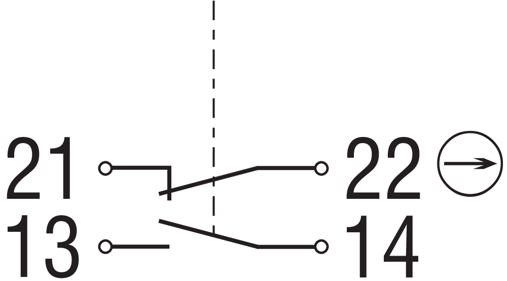
| Switching element |
1 Schließer (NO), 1 Öffner (NC) |
| Switching principle |
Sprungschaltung |
| Material of the contacts, electrical |
Silber |
Note
| Note (General) |
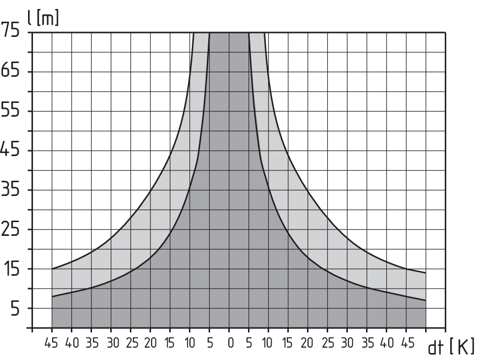
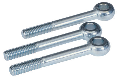
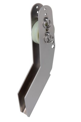
Bei Abspannlängen über 10 m sind Seilunterstützungen nach jeweils 3 bis 5 m erforderlich. Empfohlene Seillänge bei Seilzug-Notschaltern in Abhängigkeit von dem Umgebungstemperaturbereich. Da sich bei Seilzug die Seilkauschen verformen, sollte das Seil nach der Montage mehrmals kräftig gezogen werden. Anschließend sollte das Seil über die Augenschraube bzw. ein Spannschloss nachgespannt werden. In Abständen von 2 bis 5 Metern ist jeweils eine Seilunterstützung erforderlich, siehe Zubehör Die einschraubbare Meldeleuchte G24-M20 muss separat bestellt werden, siehe Zubehör. |
Sprachfilter
Datenblatt
Betriebsanleitung und Konformitätserklärung
CCC-Zertifikat
UL-Zertifikat
SISTEMA-VDMA Bibliothek/Library
Download der aktuellen Version von Adobe Reader
Produktbild (Katalogeinzelphoto )
Maßzeichnung Grundgerät
Kontaktbild
Funktionsweise
Kennliniendiagramm
Funktionsweise
Funktionsweise
Funktionsweise
Funktionsweise
Funktionsweise
| EU-Konformitätserklärung |  |
| Original | Schmersal India Private Limited G-7/1, MIDC, Ranjangaon Tal. Shirur, Dist. Pune – 412 220 Maharashtra India Internet: www.schmersal.in |
| Erklärung: | Hiermit erklären wir, dass die nachfolgend aufgeführten Bauteile aufgrund der Konzipierung und Bauart den Anforderungen der unten angeführten Europäischen Richtlinien entsprechen. |
| Bezeichnung des Bauteils: | ZQ901 |
| Typ: | siehe Typenschlüssel |
| Beschreibung des Bauteils: | Seilzug-Notschalter |
| Einschlägige Richtlinien: | Maschinenrichtlinie | 2006/42/EG |
| RoHS-Richtlinie | 2011/65/EU |
| Angewandte Normen: | EN 60947-5-1:2017 + AC:2020 EN 60947-5-5:1997 + A1:2005 + A11:2013 + A2:2017 EN 620:2002 + A1:2010 EN ISO 13850:2015 |
| Bevollmächtigter für die Zusammenstellung der technischen Unterlagen: | Oliver Wacker Möddinghofe 30 42279 Wuppertal |
| Ort und Datum der Ausstellung: | Pune, 21. September 2023 |
 |
| Rechtsverbindliche Unterschrift Sagar Jeevan Bhosale Geschäftsführer |
Schmersal India Pvt. Ltd., Plot No - G-7/1, Ranjangaon MIDC, Tal. - Shirur, Dist.- Pune 412 220
Die genannten Daten und Angaben wurden sorgfältig geprüft. Abbildungen können vom Original abweichen. Weitere technische Daten finden Sie in der Betriebsanleitung. Technische Änderungen und Irrtümer vorbehalten.
Generiert am: 21.09.2025, 17:46
.png?id=497683c97d2c2689df20070a5453bdbb)
