ZQ901-11

ZQ901-11
- Stainless steel enclosure
- one-side operation / wire up to 75 m long
- Release push button
- Position indicator
- Robust design
- Large wiring compartment
- Twisting of towing eye not possible
- External watertight collar
- wire pull and breakage detection
- 3 cable entries M 20 x 1.5
Ordering data
| Product type description |
ZQ901-11 |
| Article number (order number) |
137000450 |
| EAN (European Article Number) |
8905236108228 |
Approvals - Standards
|
CCC |
General data
| Standards |
EN ISO 13850 EN IEC 60947-5-1 EN IEC 60947-5-5 |
| Housing material |
Stainless steel (V4A) |
| Length of the wire, maximum |
75 m |
| Gross weight |
2,146 g |
General data - Features
| Indicator lamp |
No |
| Number of auxiliary contacts |
1 |
| Number of safety contacts |
1 |
| Safety classification |
| Standards |
EN ISO 13849-1 |
| Mission time |
20 Year(s) |
Safety classification - Safety outputs
| B10D Normally-closed contact (NC) |
100,000 Operations |
Mechanical data
| Mechanical life, minimum |
1,000,000 Operations |
Mechanical data - Connection technique
| Termination |
Screw terminals M20 x 1.5 |
| Cable section, minimum |
0.75 mm² |
| Cable section, maximum |
2.5 mm² |
| Note |
All indications including the conductor ferrules. |
Mechanical data - Dimensions
| Length of sensor |
75 mm |
| Width of sensor |
73 mm |
| Height of the Sensor, minimum |
220 mm |
| Height of the Sensor, maximum |
236 mm |
Ambient conditions
| Degree of protection |
IP65 IP67 IP69 |
| Ambient temperature |
-25 ... +70 °C |
| Relative humidity, minimum |
30 % |
| Relative humidity, maximum |
95 % |
Ambient conditions - Insulation values
| Rated insulation voltage Ui |
500 V |
| Rated impulse withstand voltage Uimp |
6 kV |
Electrical data
| Thermal test current |
6 A |
| Utilisation category AC-15 |
230 VAC |
| Utilisation category AC-15 |
4 A |
| Utilisation category DC-13 |
24 VDC |
| Utilisation category DC-13 |
1 A |
| Switching element |
1 NO contact, 1 NC contacts |
| Switching principle |
Snap action |
| Material of the contacts, electrical |
Silver |
Note
| Note (General) |
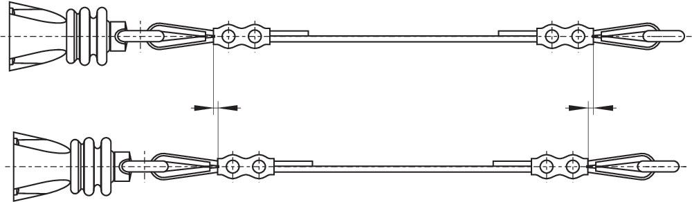
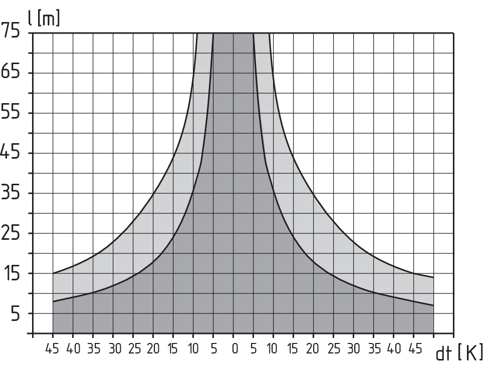
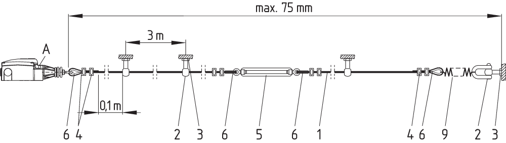
For lengths of over 10 m, intermediate wire supports must be installed every 3 to 5 m. Recommended cable lengths for pull-wire Emergency-Stop switches in relation to the range of ambient temperature. As the thimbles are subject to deformation in case of wire pull, the wire should be pulled several times after fitting. After that, the wire must be re-tensioned using the eyebolt or the tensioner. At 2 m ... 5 m distance intermediate wire supports are required, see accessories The screwed G24-M20 indicator lamp must be ordered separately, see accessories. |
Language filter
Datasheet
Operating instructions and Declaration of conformity
CCC certification
SISTEMA-VDMA library
Download the latest version of Adobe Reader
Product picture (catalogue individual photo)
Dimensional drawing basic component

Diagram
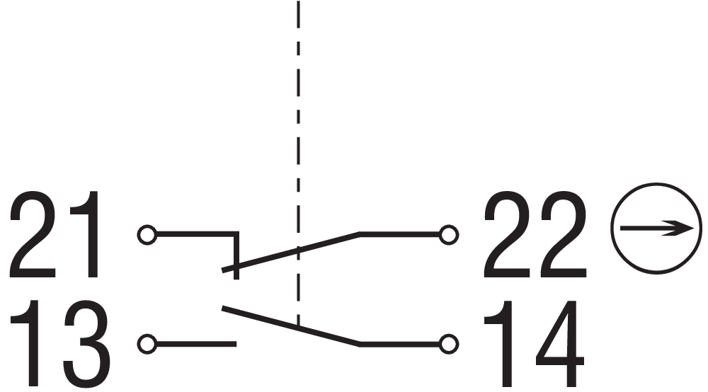
Operating principle
Characteristic curve
Operating principle
Operating principle

Operating principle

Operating principle

Operating principle


101190917 DUPLEX WIRE CLAMP 3 MM (STAINLESS STEEL)
- for Wire rope Ø 3 mm
101196043 WIRE CLAMP SZ. 3 EGG-SHAPED OFFS.
- for Wire rope Ø 3 mm
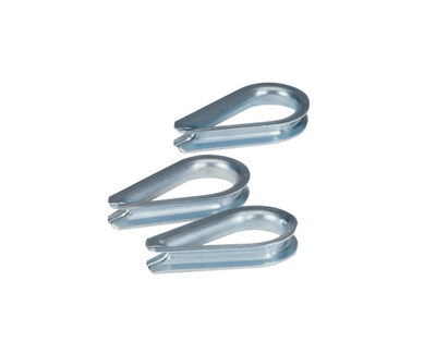
101203472 ACC-PWR-WT-3MM-NIRO
- for Wire rope Ø 3 mm
- to DIN 6899

101203476 ACC-PWR-WT-5MM-NIRO
- for Wire rope Ø 5 mm
- to DIN 6899
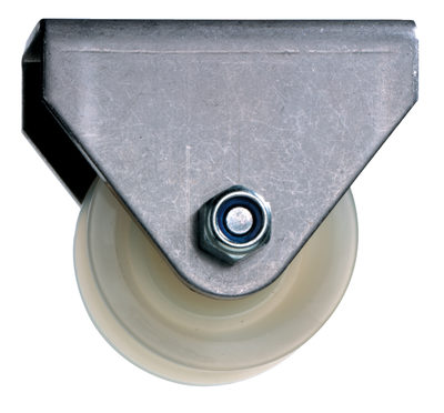
101192433 ACC-PWR-PLY-S
- To guide the wire rope where the path is not a straight line
- for Wire rope Ø 5 mm
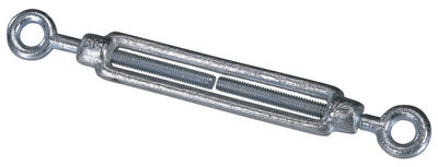
101087930 ACC-PWR-TB-M6-2
- For exact adjustment of the tension of the wire rope
- to DIN 1480
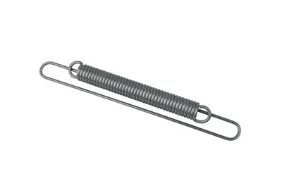
103033772 ACC-RS900-TS
- To maintain the reaction force
101186490 ACC-PWR-SKL-A0,16-VA
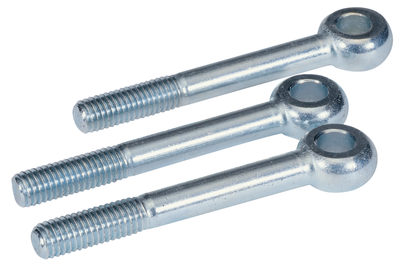
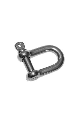
- Shackle for fixing the wire rope to the eyebolt
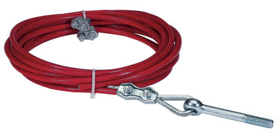
103003628 PWR-5M-SET
- With red PVC sheath
- Ready-to-fit
103003629 PWR-10M-SET
- With red PVC sheath
- Ready-to-fit
103003865 PWR-15M-SET
- With red PVC sheath
- Ready-to-fit
103003866 PWR-20M-SET
- With red PVC sheath
- Ready-to-fit
103003630 PWR-30M-SET
- With red PVC sheath
- Ready-to-fit
103003867 PWR-40M-SET
- With red PVC sheath
- Ready-to-fit
103003631 PWR-50M-SET
- With red PVC sheath
- Ready-to-fit
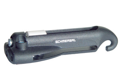
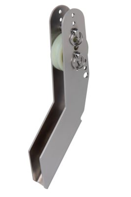
101186704 S 900
- Smooth adjustment
- Only one tool
- Antiskid
- Time-saving
- Ergonomic
- No risk of injury
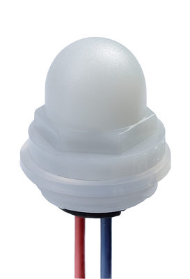
101150877 INDICATOR LAMP G24 -M20
- red LED and green LED
- To be screwed in cable entries M 20 x 1.5
- white lens (clear)
101186263 ACC-IL-G24-M20-OR
- amber LED, white lens (clear)
- To be screwed in cable entries M 20 x 1.5
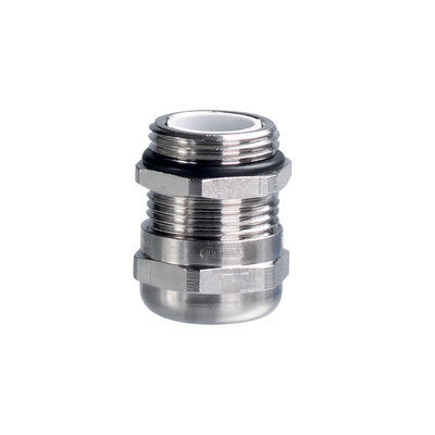
103006011 ACC-CGLD-M20-MS
- cable gland M20
- Metal film
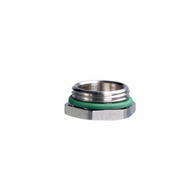
103006009 ACC-BPL-M20-MS
- Locking screw M20
- Metal film
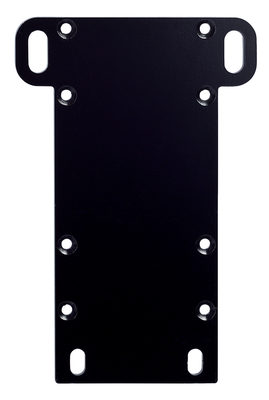
101193805 MOUNTING PLATE SET Z/TQ900 -441/75
- Mounting plate set for ZQ 900 / TQ 900
Schmersal India Pvt. Ltd., Plot No - G-7/1, Ranjangaon MIDC, Tal. - Shirur, Dist.- Pune 412 220
The details and data referred to have been carefully checked. Images may diverge from original. Further technical data can be found in the manual. Technical amendments and errors possible.
Generated on: 20/11/2024, 4:21 pm