AES 6112

AES 6112
Downloads
- NOTICE: Not available! (Replacement: AES 1112)
- Monitoring of BNS range magnetic safety sensors
- 1 safety contact, STOP 0
Ordering data
| Note (Delivery capacity) |
Niedostępne! |
| Product type description |
AES 6112 |
| Article number (order number) |
101112461 |
| EAN (European Article Number) |
4030661058443 |
| eCl@ss number, version 12.0 |
27-37-18-19 |
| eCl@ss number, version 11.0 |
27-37-18-19 |
| eCl@ss number, version 9.0 |
27-37-18-19 |
| ETIM number, version 7.0 |
EC001449 |
| ETIM number, version 6.0 |
EC001449 |
Approvals - Standards
| Certificates |
cULus |
General data
| Standards |
BG-GS-ET-14 BG-GS-ET-20 EN IEC 62061 EN ISO 13849-1 EN IEC 60947-5-1 EN IEC 60947-5-3 EN IEC 60947-5-5 EN IEC 60204-1 EN IEC 60947-1 |
| Housing material |
Tworzywo, Tworzywo termoplastyczne wzmocnione włóknem szklanym |
| Gross weight |
125 g |
General data - Features
| Wire breakage detection |
Tak |
| Cross-circuit detection |
Tak |
| Automatic reset function |
Tak |
| Reset after disconnection of supply voltage |
Tak |
| Integral system diagnostics, status |
Tak |
| Number of LEDs |
1 |
| Number of normally closed (NC) |
4 |
| Number of normally open (NO) |
2 |
| Number of safety contacts |
1 |
| Safety classification |
| Vorschriften |
EN ISO 13849-1 EN IEC 61508 |
| Stop-Category |
0 |
| Safety classification - Relay outputs |
| Performance Level, up to |
d |
| Category |
3 |
| PFH value |
1,00 x 10⁻⁷ /h |
| Notice |
do maks. 50 000 cykli przełączania / rok i maks. obciążenia styków 80% |
| Safety Integrity Level (SIL), suitable for applications in |
2 |
| Mission time |
20 Year(s) |
Mechanical data
| Mechanical lifetime, minimum |
50.000.000 Operations |
| Mounting |
montaż na standardowej szynie DIN wg EN 60715 |
Mechanical data - Connection technique
| Termination |
sztywny lub elastyczny Połączenie śrubowe M20 x 1.5 |
| Cable section, maximum |
1,5 mm² |
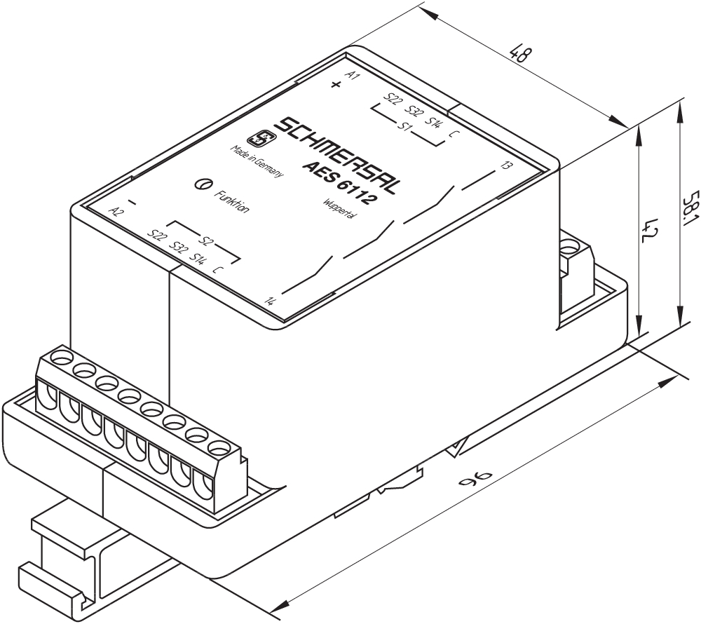
Mechanical data - Dimensions
| Width |
48 mm |
| Height |
96 mm |
| Depth |
58 mm |
Ambient conditions
| Degree of protection of the enclosure |
IP40 |
| Degree of protection of the installation space |
IP54 |
| Degree of protection of clips or terminals |
IP20 |
| Ambient temperature |
+0 ... +55 °C |
| Storage and transport temperature |
-25 ... +70 °C |
| Resistance to vibrations |
10...55 Hz, amplituda 0,35 mm, ± 15 % |
| Restistance to shock |
30 g / 11 ms |
Ambient conditions - Insulation values
| Rated impulse withstand voltage Uimp |
4,8 kV |
| Overvoltage category |
III |
| Degree of pollution |
2 |
Electrical data
| Frequency range |
50 Hz 60 Hz |
| Operating voltage |
24 VDC -15 % / +15 % |
| Thermal test current |
5 A |
| Rated operating voltage |
24 VDC |
| Operating current |
100 mA |
| Rated AC voltage for controls, 50 Hz, minimum |
20.4 |
| Rated control voltage at AC 50 Hz, maximum |
26.4 |
| Rated AC voltage for controls, 60 Hz, minimum |
20.4 |
| Rated control voltage at AC 60 Hz, maximum |
26.4 |
| Rated AC voltage for controls at DC minimum |
20,4 VDC |
| Rated control voltage at DC, maximum |
27,6 VDC |
| Electrical power consumption |
2,5 W |
| Contact resistance, maximum |
0,1 Ω |
| Note (Contact resistance) |
w nowym stanie |
| Drop-out delay in case of power failure, typically |
80 ms |
| Drop-out delay in case of emergency, typically |
20 ms |
| Pull-in delay at automatic start, maximum, typically |
100 ms |
| Pull-in delay at RESET, typically |
20 ms |
| Material of the contacts, electrical |
AgCdO |
Electrical data - Safe relay outputs
| Voltage, Utilisation category AC-15 |
230 VAC |
| Current, Utilisation category AC-15 |
6 A |
| Voltage, Utilisation category DC-13 |
24 VDC |
| Current, Utilisation category DC-13 |
6 A |
| Switching capacity, minimum |
10 VDC |
| Switching capacity, minimum |
10 mA |
| Switching capacity, maximum |
250 VAC |
| Switching capacity, maximum |
8 A |
Electrical data - Digital inputs
| Conduction resistance, maximum |
40 Ω |
Electrical data - Relay outputs (auxiliary contacts)
| Switching capacity, maximum |
24 VDC |
| Switching capacity, maximum |
2 A |
Electrical data - Electromagnetic compatibility (EMC)
| EMC rating |
EN 61000-4-3 EN 61000-4-6 IEC 61000-6-2 |
Status indication
| Indicated operating states |
Operacja uprawniona |
Other data
| Note (applications) |
Czujnik bezpieczeństwa Osłony bezpieczeństwa |
Note
| Note (General) |
Obciążenia indukcyjne (np. styczniki, przekaźniki itp.) należy wytłumić przy pomocy odpowiedniego obwodu. |
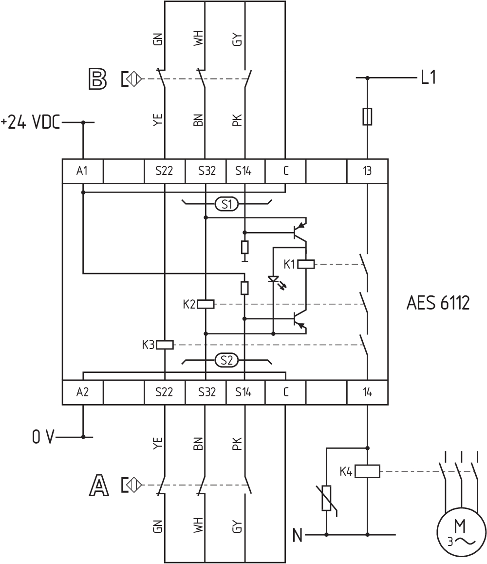
Wiring example
| Note (Wiring diagram) |
Do zabezpieczenia jednej lub wielu osłon bezpieczeństwa, PL do c i Kategoria 1 Monitorowanie kilku osłon z wykorzystaniem magnetycznych czujników bezpieczeństwa typoszeregu BNS Schemat okablowania dla zamknietej osłony bezpieczeńatwa i stanu z wyłączonym zasilaniem. Monitorowanie kolejnych osłon: Kolejne magnetyczne czujniki bezpieczeństwa można podłączyć do S2 w podobny sposób, jak w przypadku podłączonych do S1. |
Filtr językowy
Karta katalogowa
Instrukcja obsługi i deklaracja zgodności
Certyfikat UL
Przykład połączeń (okablowanie elektryczne)
pobierz najnowszą wersję Adobe Reader
Zdjęcie produktu (pojedyncze zdjęcie katalogowe)
Rysunek wymiarowy Urządzenie podstawowe
Przykład okablowania
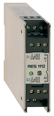
101128982 AES 1112 24 VDC
- Monitoring of BNS range magnetic safety sensors
- 1 safety contact, STOP 0
Schmersal India Pvt. Ltd., Plot No - G-7/1, Ranjangaon MIDC, Tal. - Shirur, Dist.- Pune 412 220
Dane zostały starannie sprawdzone. Zdjęcia mogą odbiegać od rzeczywistości. Dalsze dane techniczne znajdują się w instrukcji obsługi. Możliwe są zmiany i błędy techniczne.
Wygenerowano dnia 12.08.2025, 00:38
Ostatnio oglądane