AES 6112

AES 6112
Downloads
- NOTICE: Not available! (Replacement: AES 1112)
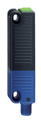
- Monitoring of BNS range magnetic safety sensors
- 1 safety contact, STOP 0
Ordering data
| Note (Delivery capacity) |
Not available! |
| Product type description |
AES 6112 |
| Article number (order number) |
101112461 |
| EAN (European Article Number) |
4030661058443 |
| eCl@ss number, version 12.0 |
27-37-18-19 |
| eCl@ss number, version 11.0 |
27-37-18-19 |
| eCl@ss number, version 9.0 |
27-37-18-19 |
| ETIM number, version 7.0 |
EC001449 |
| ETIM number, version 6.0 |
EC001449 |
Approvals - Standards
| Certificates |
cULus |
General data
| Standards |
BG-GS-ET-14 BG-GS-ET-20 EN IEC 62061 EN ISO 13849-1 EN IEC 60947-5-1 EN IEC 60947-5-3 EN IEC 60947-5-5 EN IEC 60204-1 EN IEC 60947-1 |
| Housing material |
Glass-fibre, reinforced thermoplastic |
| Gross weight |
125 g |
General data - Features
| Wire breakage detection |
Yes |
| Cross-circuit detection |
Yes |
| Automatic reset function |
Yes |
| Reset after disconnection of supply voltage |
Yes |
| Integral system diagnostics, status |
Yes |
| Number of LEDs |
1 |
| Number of normally closed (NC) |
4 |
| Number of normally open (NO) |
2 |
| Number of safety contacts |
1 |
| Safety classification |
| Vorschriften |
EN ISO 13849-1 EN IEC 61508 |
| Stop-Category |
0 |
| Safety classification - Relay outputs |
| Performance Level, up to |
d |
| Category |
3 |
| PFH value |
1.00 x 10⁻⁷ /h |
| Notice |
for max. 50,000 switching cycles/year and max. 80% contact load |
| Safety Integrity Level (SIL), suitable for applications in |
2 |
| Mission time |
20 Year(s) |
Mechanical data
| Mechanical life, minimum |
50,000,000 Operations |
| Mounting |
Snaps onto standard DIN rail to EN 60715 |
Mechanical data - Connection technique
| Termination |
rigid or flexible Screw terminals M20 x 1.5 |
| Cable section, maximum |
1.5 mm² |
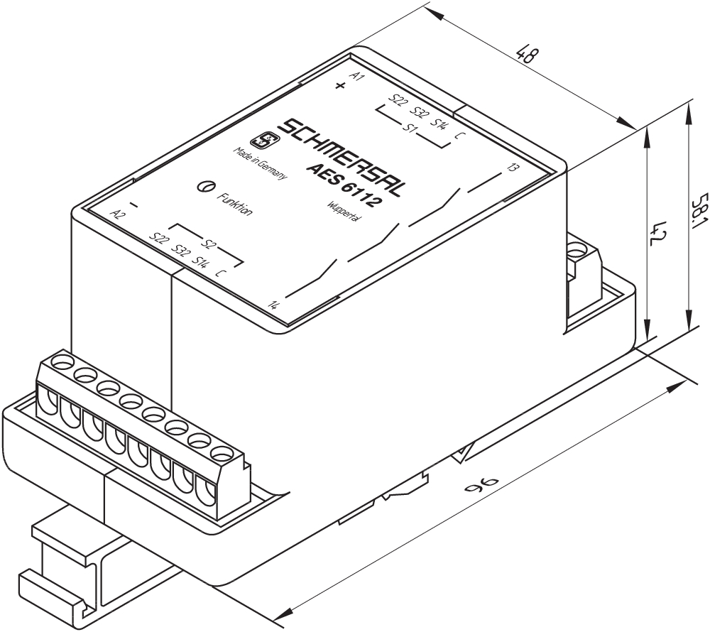
Mechanical data - Dimensions
| Width |
48 mm |
| Height |
96 mm |
| Depth |
58 mm |
Ambient conditions
| Degree of protection of the enclosure |
IP40 |
| Degree of protection of the mounting space |
IP54 |
| Degree of protection of clips or terminals |
IP20 |
| Ambient temperature |
+0 ... +55 °C |
| Storage and transport temperature |
-25 ... +70 °C |
| Resistance to vibrations |
10...55 Hz, Amplitude 0.35 mm, ± 15 % |
| Restistance to shock |
30 g / 11 ms |
Ambient conditions - Insulation values
| Rated impulse withstand voltage Uimp |
4.8 kV |
| Overvoltage category |
III |
| Degree of pollution |
2 |
Electrical data
| Frequency range |
50 Hz 60 Hz |
| Operating voltage |
24 VDC -15 % / +15 % |
| Thermal test current |
5 A |
| Rated operating voltage |
24 VDC |
| Operating current |
100 mA |
| Rated AC voltage for controls, 50 Hz, minimum |
20.4 |
| Rated control voltage at AC 50 Hz, maximum |
26.4 |
| Rated AC voltage for controls, 60 Hz, minimum |
20.4 |
| Rated control voltage at AC 60 Hz, maximum |
26.4 |
| Rated AC voltage for controls at DC minimum |
20.4 VDC |
| Rated control voltage at DC, maximum |
27.6 VDC |
| Electrical power consumption |
2.5 W |
| Contact resistance, maximum |
0.1 Ω |
| Note (Contact resistance) |
in new state |
| Drop-out delay in case of power failure, typically |
80 ms |
| Drop-out delay in case of emergency, typically |
20 ms |
| Pull-in delay at automatic start, maximum, typically |
100 ms |
| Pull-in delay at RESET, typically |
20 ms |
| Material of the contacts, electrical |
AgCdO |
Electrical data - Safe relay outputs
| Voltage, Utilisation category AC-15 |
230 VAC |
| Current, Utilisation category AC-15 |
6 A |
| Voltage, Utilisation category DC-13 |
24 VDC |
| Current, Utilisation category DC-13 |
6 A |
| Switching capacity, minimum |
10 VDC |
| Switching capacity, minimum |
10 mA |
| Switching capacity, maximum |
250 VAC |
| Switching capacity, maximum |
8 A |
Electrical data - Digital inputs
| Conduction resistance, maximum |
40 Ω |
Electrical data - Relay outputs (auxiliary contacts)
| Switching capacity, maximum |
24 VDC |
| Switching capacity, maximum |
2 A |
Electrical data - Electromagnetic compatibility (EMC)
| EMC rating |
EN 61000-4-3 EN 61000-4-6 IEC 61000-6-2 |
Status indication
| Indicated operating states |
Authorised operation |
Other data
| Note (applications) |
Safety sensor Guard system |
Note
| Note (General) |
Inductive loads (e.g. contactors, relays, etc.) are to be suppressed by means of a suitable circuit. |
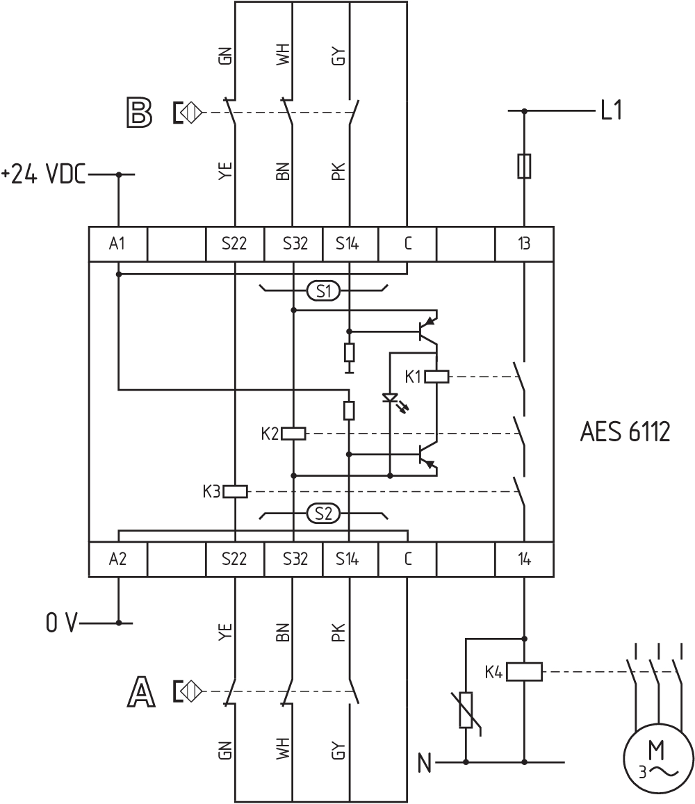
Wiring example
| Note (Wiring diagram) |
To secure one or a number of guard doors up to PL c and Category 1 Monitoring a number of guard doors using magnetic safety sensors BNS range The wiring diagram is shown with guard doors closed and in de-energised condition. Monitoring further guard doors: Further magnetic safety sensors can be connected to S2 in a similar way to those on S1. |
Language filter
Datasheet
Operating instructions and Declaration of conformity
UL Certificate
Wiring example (electr. wiring)
Download the latest version of Adobe Reader
Product picture (catalogue individual photo)
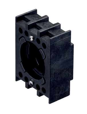
Dimensional drawing basic component
Wiring example
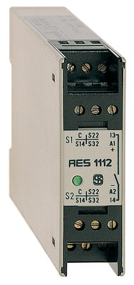
101128982 AES 1112 24 VDC
- Monitoring of BNS range magnetic safety sensors
- 1 safety contact, STOP 0
K.A. Schmersal GmbH & Co. KG, Möddinghofe 30, 42279 Wuppertal
The details and data referred to have been carefully checked. Images may diverge from original. Further technical data can be found in the manual. Technical amendments and errors possible.
Generated on: 06/07/2025, 06:28
Recently viewed
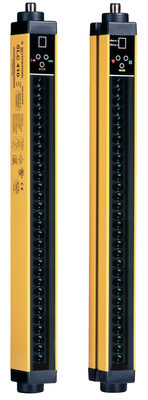
SLG 410-E/R0500-02-RFS
RSS 36-I2-D-ST-DU
ACC-RS65X-TS
BDF200-SD-NHK-SWS20-WS30-LTWH-G24
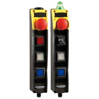
SLC440COM-ER-0490-30-H

TA 471-03/03Y-H-RMS -840
A-K3P-M12-S-W-2M-OG-1- 1LP-A-2
PSC1-C-10-FB1-ECFS