SRB301ST-24V-(V.3)

SRB301ST-24V-(V.3)
- Suitable for the signal processing of outputs with contact sensors
- Suitable for signal processing of outputs connected to potentials (AOPDs), e.g. safety light grids/curtains
- Suitable for the signal processing of outputs with contact sensors
- 3 safety contacts, STOP 0
- 1 Signalling output
Ordering data
| Product type description |
SRB301ST-24V-(V.3) |
| Article number (order number) |
103002205 |
| EAN (European Article Number) |
4030661562186 |
| eCl@ss number, version 12.0 |
27-37-18-19 |
| eCl@ss number, version 11.0 |
27-37-18-19 |
| eCl@ss number, version 9.0 |
27-37-18-19 |
| ETIM number, version 7.0 |
EC001449 |
| ETIM number, version 6.0 |
EC001449 |
| Notice |
Auslaufprodukt |
Approvals - Standards
| Certificates |
TÜV cULus CCC TILVA |
General data
| Standards |
EN IEC 62061 EN 81-20/-50 EN ISO 13849-1 EN IEC 60947-5-1 EN IEC 60947-5-3 EN IEC 60947-5-5 EN IEC 61508 EN IEC 60204-1 EN IEC 60947-1 |
| Climatic stress |
EN 60068-2-78 |
| Housing material |
Kunststoff, glasfaserverstärkter Thermoplast, belüftet |
| Gross weight |
250 g |
General data - Features
| Electronic Fuse |
Ja |
| Wire breakage detection |
Ja |
| Cross-circuit detection |
Ja |
| Removable Terminals |
Ja |
| Start input |
Ja |
| Feedback circuit |
Ja |
| Automatic reset function |
Ja |
| Reset edge detection |
Ja |
| Earth connection detection |
Ja |
| Integral system diagnostics, status |
Ja |
| Number of auxiliary contacts |
1 |
| Number of LEDs |
5 |
| Number of normally closed (NC) |
2 |
| Number of safety contacts |
3 |
| Safety classification |
| Vorschriften |
EN ISO 13849-1 EN IEC 62061 EN IEC 61508 |
| Stop-Category |
0 |
| Safety classification - Relay outputs |
| Performance Level, stop 0, up to |
e |
| Category, Stop 0 |
4 |
| Diagnostic Coverage (DC) Level, Stop 0 |
≥ 99 % |
| PFH value, Stop 0 |
2,00 x 10⁻⁸ /h |
| Safety Integrity Level (SIL), Stop 0, suitable for applications in |
3 |
| Mission time |
20 Year(s) |
| Common Cause Failure (CCF), minimum |
65 |
Mechanical data
| Mechanical life, minimum |
10.000.000 Operations |
| Mounting |
Schnellbefestigung für Normschiene nach DIN EN 60715 |
Mechanical data - Connection technique
| Terminal designations |
IEC/EN 60947-1 |
| Termination |
starr oder flexibel Schraubanschluss, steckbar |
| Cable section, minimum |
0,25 mm² |
| Cable section, maximum |
2,5 mm² |
| Tightening torque of Clips |
0,6 Nm |
Mechanical data - Dimensions
| Width |
22,5 mm |
| Height |
120 mm |
| Depth |
121 mm |
Ambient conditions
| Degree of protection of the enclosure |
IP40 |
| Degree of protection of the mounting space |
IP54 |
| Degree of protection of clips or terminals |
IP20 |
| Ambient temperature |
-25 ... +60 °C |
| Storage and transport temperature |
-40 ... +85 °C |
| Resistance to vibrations |
10 ... 55 Hz, Amplitude 0,35 mm |
| Restistance to shock |
30 g / 11 ms |
Ambient conditions - Insulation values
| Rated impulse withstand voltage Uimp |
4 kV |
| Overvoltage category |
III |
| Degree of pollution |
2 |
Electrical data
| Frequency range |
50 Hz 60 Hz |
| Operating voltage |
24 VAC -15 % / +10 % |
| Ripple voltage |
10 % |
| Rated operating voltage |
24 VAC |
| Rated operating voltage |
24 VDC |
| Rated AC voltage for controls, 50 Hz, minimum |
20,4 VAC |
| Rated control voltage at AC 50 Hz, maximum |
26,4 VAC |
| Rated AC voltage for controls, 60 Hz, minimum |
20,4 VAC |
| Rated control voltage at AC 60 Hz, maximum |
26,4 VAC |
| Rated AC voltage for controls at DC minimum |
20,4 VDC |
| Rated control voltage at DC, maximum |
28,8 VDC |
| Electrical power consumption |
2 W |
| Electrical power consumption |
4,9 VA |
| Contact resistance, maximum |
0,1 Ω |
| Note (Contact resistance) |
in Neuzustand |
| Drop-out delay in case of power failure, typically |
80 ms |
| Drop-out delay in case of emergency, typically |
20 ms |
| Pull-in delay at automatic start, maximum, typically |
100 ms |
| Pull-in delay at RESET, typically |
20 ms |
| Material of the contacts, electrical |
AgSnO, selbstreinigend, zwangsgeführt |
Electrical data - Safe relay outputs
| Voltage, Utilisation category AC-15 |
230 VAC |
| Current, Utilisation category AC-15 |
6 A |
| Voltage, Utilisation category DC-13 |
24 VDC |
| Current, Utilisation category DC-13 |
6 A |
| Switching capacity, minimum |
10 VDC |
| Switching capacity, minimum |
10 mA |
| Switching capacity, maximum |
250 VAC |
| Switching capacity, maximum |
8 A |
Electrical data - Digital inputs
| Conduction resistance, maximum |
40 Ω |
Electrical data - Relay outputs (auxiliary contacts)
| Switching capacity, maximum |
24 VDC |
| Switching capacity, maximum |
2 A |
Electrical data - Electromagnetic compatibility (EMC)
| EMC rating |
EMV-Richtlinie |
Status indication
| Note (LED switching conditions display) |
QS: Status Querschlusserkennung (LED leuchtet, wenn Querschlusserkennung aktiviert ist). |
| Indicated operating states |
Stellung der Relais K2 Stellung der Relais K1 Interne Betriebsspannung Ui |
Other data
| Note (applications) |
Sicherheits-Sensor Schutzeinrichtung NOT-HALT-Taster Seilzug-Notschalter Sicherheits-Lichtschranken |
Note
| Note (General) |
Induktive Verbraucher (Schütze, Relais etc.) sind durch eine geeignete Beschaltung zu entstören. |
Wiring example
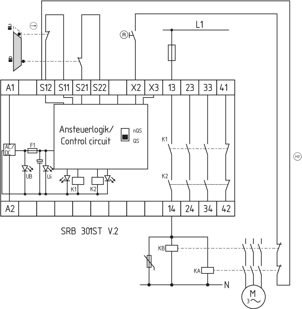
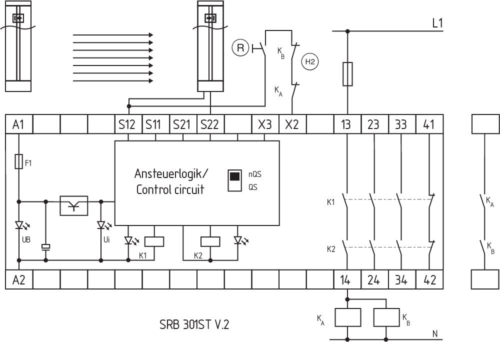
| Note (Wiring diagram) |
Das Schaltungsbeispiel ist bei geschlossenen Schutzeinrichtungen und im spannungslosen Zustand dargestellt. Eingangsebene: 2-kanalige Ansteuerung, dargestellt am Beispiel einer Schutztürüberwachung mit zwei Positionsschaltern, davon einer zwangsöffnend, externem Reset-Taster (R) und Rückführkreis (H2). Leistungsebene: 2-kanalige Ansteuerung geeignet zur Kontaktverstärkung bzw. Kontaktvervielfältigung durch Schütze oder Relais mit zwangsgeführten Kontakten. Die Ansteuerung erkennt Querschlüsse, Drahtbrüche und Erdschlüsse im Überwachungskreis. Einstellung des Schalters: Die Programmierung auf die Funktion Querschlusserkennung (Auslieferzustand) erfolgt durch den Schalter unter der Frontabdeckung des Bausteins: Position nQS (oben): nicht querschlusssicher, geeignet für einkanalige Applikationen und Applikationen mit potenzialbehafteten Ausgängen in den Ansteuerkreisen. Position QS (unten): querschlusssicher, geeignet für zweikanalige Applikationen ohne potenzialbehaftete Ausgänge in den Ansteuerkreisen. Bei 1-kanaliger Ansteuerung den Öffnerkontakt S11/S12 anschließen und S12/S22 brücken (QS-Schalter = nQS) Potenzialbehaftete Ausgänge von Lichtgittern/-vorhängen (p-schaltend) an S12/S22 anschließen. Die Geräte müssen auf gleichem Bezugspotenzial liegen. (QS-Schalter = nQS) Automatischer Start: Die Programmierung auf automatischen Start erfolgt durch die Einbindung des Rückführkreises an die Klemmen S12/X3. Bei nicht benötigtem Rückführkreis ist dieser durch eine Brücke zu ersetzen. F1 = Hybridsicherung |
Sprachfilter
Datenblatt
Betriebsanleitung und Konformitätserklärung
UKCA Konformitätserklärung
UL-Zertifikat
TILVA-Zertifikat
Baumusterprüfbescheinigung
TÜV-Zertifikat
CCC-Zertifikat
Schaltungsbeispiel (elektr. Verdrahtung)
SISTEMA-VDMA Bibliothek/Library
Download der aktuellen Version von Adobe Reader
Produktbild (Katalogeinzelphoto )
Schaltungsbeispiel
Schaltungsbeispiel
Schaltungsbeispiel
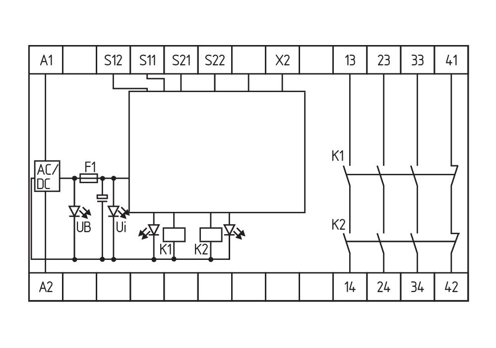
Symbol (technischer Standard)


103007672 SRB-E-301ST
- Plug-in screw terminals with coding
- STOP 0 Function
- 1 oder 2-channel control
- Start button / Auto-start
- 1 Auxiliary contact
- 3 safety contacts
| UK Declaration of Conformity |  |
| Company: | K.A. Schmersal GmbH & Co. KG Möddinghofe 30 42279 Wuppertal Germany Internet: www.schmersal.com |
| Declaration: | We hereby, under sole responsibility, certify that the hereafter described components both in their basic design and construction conform to the relevant statutory requirements, regulations and designated standards of the United Kingdom. |
| Name of the component: | SRB301STV.2, SRB301ST/CCV.2, SRB301ST/PCV.2, SRB301STV.3, SRB301ST/CCV.3, SRB301ST/PCV.3 |
| Year of construction: | see enclosure seal SRB301ST... |
| Description of the component: | Safety relay module for emergency stop circuits, guard door monitoring, magnetic safety switches, AOPDs and for use in firing systems |
| Relevant legislation: | Supply of Machinery (Safety) Regulations 1) | 2008 |
| Electromagnetic Compatibility Regulations | 2016 | |
| Lift regulations 2) | 2016 | |
| The Restriction of the Use of Certain Hazardous Substances in Electrical and Electronic Equipment Regulations | 2012 |
| Designated standards: | EN 50156-1:2015 EN 60947-5-1:2017 + AC:2020 EN 60947-5-3:2013 EN ISO 13850:2015 EN 81-20:2020 EN 81-50:2020 EN ISO 13849-1:2015 |
| Approved body for Type Examination: | TÜV Rheinland Industrie Service GmbH Am Grauen Stein, 51105 Köln ID n°: 0035 |
| Type examination certificate: | 1) 01/205/5284.02/22 2) 01/208/4A/6110.01/21 |
| UK-Importer / Person authorised for the compilation of the technical documentation: | Schmersal UK Ltd. Paul Kenney Unit 1, Sparrowhawk Close Enigma Business Park Malvern, Worcestershire, WR14 1GL |
| Place and date of issue: | Wuppertal, October 13, 2022 |
 |
| Authorised signature Philip Schmersal Managing Director |
| EU-Konformitätserklärung | |
| Original | K.A. Schmersal GmbH & Co. KG Möddinghofe 30 42279 Wuppertal Germany Internet: www.schmersal.com |
| Erklärung: | Hiermit erklären wir, dass die nachfolgend aufgeführten Bauteile aufgrund der Konzipierung und Bauart den Anforderungen der unten angeführten Europäischen Richtlinien entsprechen. |
| Bezeichnung des Bauteils: | SRB301STV.2 SRB301ST/CCV.2 SRB301ST/PCV.2 SRB301STV.3 SRB301ST/CCV.3 SRB301ST/PCV.3 |
| Baujahr: | siehe Gehäuse-Siegel SRB301ST… |
| Beschreibung des Bauteils: | Sicherheitsrelaisbaustein für Not-Halt-Schaltungen Schutztürüberwachungen, Sicherheitsmagnetschalter, AOPDs und den Einsatz in Feuerungsanlagen |
| Einschlägige Richtlinien: | Maschinenrichtlinie 1) | 2006/42/EG |
| EMV-Richtlinie | 2014/30/EU | |
| Aufzugsrichtlinie 2) | 2014/33/EU | |
| RoHS-Richtlinie | 2011/65/EU |
| Angewandte Normen: | EN 50156-1:2015 EN 60947-5-1:2017 + AC:2020 EN 60947-5-3:2013 EN ISO 13850:2015 EN 81-20:2020 EN 81-50:2020 EN ISO 13849-1:2015 |
| Benannte Stelle der Baumusterprüfung: | TÜV Rheinland Industrie Service GmbH Am Grauen Stein, 51105 Köln Kenn-Nr.: 0035 |
| EG-Baumusterprüfbescheinigung: | 1) 01/205/5284.02/22 2) 01/208/4A/6110.01/21 |
| Bevollmächtigter für die Zusammenstellung der technischen Unterlagen: | Oliver Wacker Möddinghofe 30 42279 Wuppertal |
| Ort und Datum der Ausstellung: | Wuppertal, 13. Oktober 2022 |
|
| Rechtsverbindliche Unterschrift Philip Schmersal Geschäftsführer |
Schmersal India Pvt. Ltd., Plot No - G-7/1, Ranjangaon MIDC, Tal. - Shirur, Dist.- Pune 412 220
Die genannten Daten und Angaben wurden sorgfältig geprüft. Abbildungen können vom Original abweichen. Weitere technische Daten finden Sie in der Betriebsanleitung. Technische Änderungen und Irrtümer vorbehalten.
Generiert am: 10.04.2025, 02:58
Zuletzt angesehen

U-EX-TS335-20Y
AZ201CC-T-1P2P

Z3KM476E-02-U90-230
SLC 410-E/R0910-14-BM