SRB202CS 24VDC
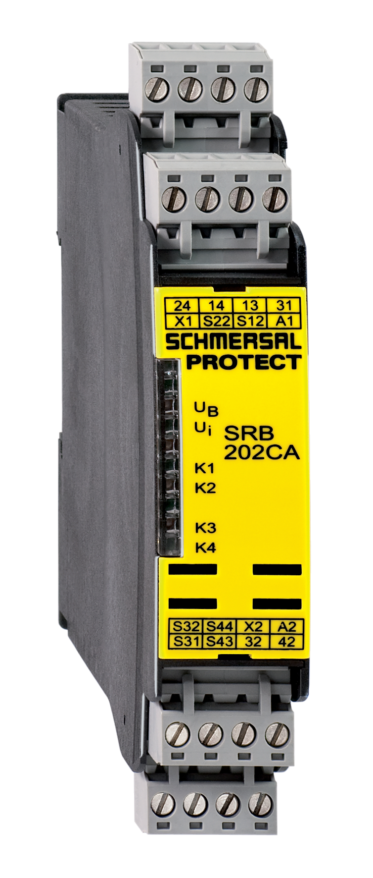
SRB202CS 24VDC
- Level 1: Reset without edge detection, Optional Automatic reset function, Level 2: / Opener (NC) Opener (NC)
- Two-functions safety monitoring module (double evaluation)
- 2 enabling paths with different shut-down behaviour, e.g. emergency exit opens both enabling paths (level 1); guard door monitoring only opens the second enabling path (level 2)
- Suitable for signal processing of potential-free contacts, e.g. Emergency Stop command devices (level 1), position switches with safety function, solenoid interlocks and safety sensors (level 2)
- 2 Signalling outputs
Ordering data
| Replacement article number |
101177154 |
| Product type description |
SRB202CS 24VDC |
| Article number (order number) |
101176208 |
| EAN (European Article Number) |
4250116201914 |
| eCl@ss number, version 12.0 |
27-37-18-19 |
| eCl@ss number, version 11.0 |
27-37-18-19 |
| eCl@ss number, version 9.0 |
27-37-18-19 |
| ETIM number, version 7.0 |
EC001449 |
| ETIM number, version 6.0 |
EC001449 |
| Notice |
Discontinued product |
Approvals - Standards
| Certificates |
cULus |
General data
| Standards |
EN IEC 62061 EN ISO 13849-1 EN IEC 60947-5-1 EN IEC 60947-5-3 EN IEC 60947-5-5 EN IEC 61508 EN IEC 60204-1 EN IEC 60947-1 |
| Climatic stress |
EN 60068-2-78 |
| Housing material |
materiale sintetico, termoplastica rinforzata con fibra di vetro, ventilata |
| Gross weight |
235 g |
General data - Features
| Electronic Fuse |
Sì |
| Wire breakage detection |
Sì |
| Removable Terminals |
Sì |
| Start input |
Sì |
| Feedback circuit |
Sì |
| Automatic reset function |
Sì |
| Earth connection detection |
Sì |
| Integral system diagnostics, status |
Sì |
| Number of auxiliary contacts |
2 |
| Number of inputs for NC |
2 |
| Number of inputs for NO |
2 |
| Number of LEDs |
6 |
| Number of safety contacts |
2 |
| Safety classification |
| Vorschriften |
EN IEC 60947-5-1 EN IEC 61508 |
| Stop-Category |
0 |
| Safety classification - Relay outputs |
| Performance Level, stop 0, up to |
e |
| Category, Stop 0 |
4 |
| Diagnostic Coverage (DC) Level, Stop 0 |
≥ 99 % |
| PFH value, Stop 0 |
2,00 x 10⁻⁸ /h |
| Safety Integrity Level (SIL), Stop 0, suitable for applications in |
3 |
| Mission time |
20 Year(s) |
| Common Cause Failure (CCF), minimum |
65 |
Mechanical data
| Mechanical life, minimum |
10.000.000 Operations |
| Mounting |
fissaggio rapido per guide DIN secondo DIN EN 60715 |
Mechanical data - Connection technique
| Terminal designations |
IEC/EN 60947-1 |
| Termination |
rigido o flessibile Collegamento a vite M20 x 1.5 |
| Cable section, minimum |
0,25 mm² |
| Cable section, maximum |
2,5 mm² |
| Tightening torque of Clips |
0,6 Nm |
Mechanical data - Dimensions
| Width |
22,5 mm |
| Height |
100 mm |
| Depth |
121 mm |
Ambient conditions
| Degree of protection of the enclosure |
IP40 |
| Degree of protection of the mounting space |
IP54 |
| Degree of protection of clips or terminals |
IP20 |
| Ambient temperature |
-25 ... +45 °C |
| Storage and transport temperature |
-40 ... +85 °C |
| Resistance to vibrations |
10 ... 55 Hz, ampiezza 0,35 mm |
| Restistance to shock |
10 g / 11 ms |
Ambient conditions - Insulation values
| Rated impulse withstand voltage Uimp |
4 kV |
| Overvoltage category |
III |
| Degree of pollution |
2 |
Electrical data
| Operating voltage |
24 VDC -10 % / +20 % |
| Ripple voltage |
10 % |
| Rated operating voltage |
24 VDC |
| Rated AC voltage for controls at DC minimum |
20,4 VDC |
| Rated control voltage at DC, maximum |
28,8 VDC |
| Electrical power consumption |
4,4 W |
| Contact resistance, maximum |
0,1 Ω |
| Note (Contact resistance) |
in perfette condizioni |
| Drop-out delay in case of power failure, typically |
80 ms |
| Drop-out delay in case of emergency, typically |
20 ms |
| Pull-in delay at automatic start, maximum, typically |
100 ms |
| ON delay at automatic start |
Regolabile |
| Pull-in delay at RESET, typically |
20 ms |
| Material of the contacts, electrical |
Ag-Ni, autopulente, azione obbligata |
Electrical data - Safe relay outputs
| Voltage, Utilisation category AC-15 |
250 VAC |
| Current, Utilisation category AC-15 |
6 A |
| Voltage, Utilisation category DC-13 |
24 VDC |
| Current, Utilisation category DC-13 |
6 A |
| Switching capacity, minimum |
10 VDC |
| Switching capacity, minimum |
10 mA |
| Switching capacity, maximum |
250 VAC |
| Switching capacity, maximum |
8 A |
Electrical data - Digital inputs
| Conduction resistance, maximum |
40 Ω |
Electrical data - Relay outputs (auxiliary contacts)
| Switching capacity, maximum |
24 VDC |
| Switching capacity, maximum |
2 A |
Electrical data - Electromagnetic compatibility (EMC)
| EMC rating |
Direttiva EMC |
Status indication
| Indicated operating states |
posizione dei relè K2 posizione dei relè K1 tensione d'esercizio interna Ui posizione dei relè K3 |
Other data
| Note (applications) |
Sensore di sicurezza Dispositivo di protezione Pulsante di arresto d'emergenza Interruttori a fune d'emergenza |
Note
| Note (General) |
Soppresori induttivi (contattore, relè ecc.) vanno ripristinati con una commutazione idonea. |
| Note (Cross-circuit detection) |
Livello 1 |
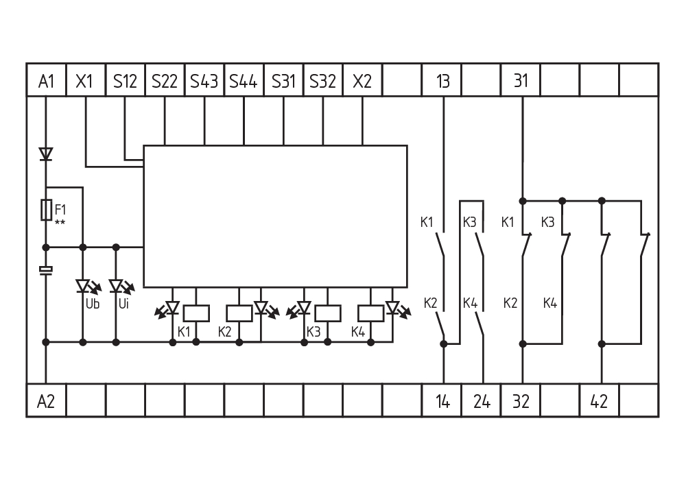
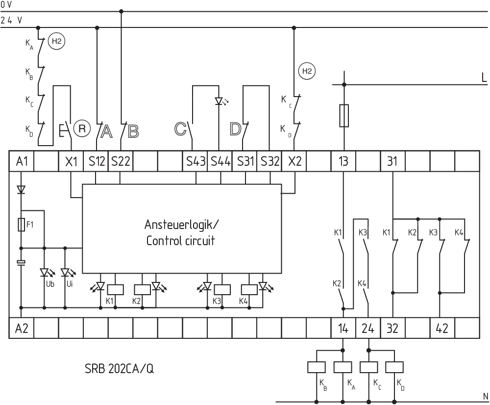
Wiring example
| Note (Wiring diagram) |
L'esempio di commutazione è rappresentato con dispositivi di sicurezza chiusi e in condizione senza tensione. Livello di performance: azionamento 2 canale, adatto per il rafforzamento, quindi la duplicazione, dei contatti mediante contattori, oppure relè con contatti ad azione obbligata. Il controllo riconosce cortocircuiti trasversali, rotture di cavo e dispersioni verso terra nel circuito sorvegliato. Livello di ingresso: circuito di comando bicanale, rappresentato con l'esempio di un circuito d'emergenza (livello 1) con un pulsante di reset esterno (R), ed un controllo di una porta di sicurezza (livello 2) con circuito di ritorno (H2). Avvio automatico: (Livello 1) La programmazione dell'avvio automatico avviene mediante integrazione del circuito di ripristino ai morsetti X1 / +24VDC. Avvio automatico: (Livello 2) La programmazione dell'avvio automatico avviene mediante integrazione del circuito di ripristino ai morsetti X2 / +24VDC. Se il circuito di ripristino non è richiesto, sostituirlo con un ponticello. 1 contatto NC per ciascuno dei livelli 1 e 2 segnala il relativo stato. |
Filtro lingua
Scheda Tecnica
Manuale d'istruzioni e dichiarazione UE di conformità
Certificazione UL
Esempio di collegamento (cablaggio elettrico)
Libreria SISTEMA-VDMA
Download dell'ultima versione di Adobe Reader
Immagine del prodotto (foto singola per catalogo)
Esempio di azionamento
Esempio di azionamento
Simbolo (standard tecnico)

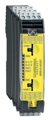
103007221 SRB-E-402ST
- Two-functions safety monitoring module (double evaluation), 2 x STOP 0
- 2 x 1 oder 2-channel control
- 2 x Start button / Auto-start
- 1 x Monitoring two-hand control panels to ISO 13851
- 2 safety contacts
- 2 Safety outputs
| EU Declaration of Conformity |  |
| Original | K.A. Schmersal GmbH & Co. KG Möddinghofe 30 42279 Wuppertal Germany Internet: www.schmersal.com |
| Declaration: | We hereby certify that the hereafter described components both in their basic design and construction conform to the applicable European Directives. |
| Name of the component: | SRB202CS / SRB202CS/T / SRB202CA / SRB202CA/T / SRB202CA/Q / SRB202CA/QT |
| Description of the component: | Safety-monitoring module for emergency stop circuits, guard door monitoring and magnetic safety switches |
| Relevant Directives: | Machinery Directive | 2006/42/EC |
| EMC-Directive | 2014/30/EU | |
| RoHS-Directive | 2011/65/EU |
| Applied standards: | EN 60947-5-1:2004 + AC:2005 + A1:2009 EN 60947-5-1:2017 EN ISO 13850:2015 EN ISO 13849-1:2015 EN ISO 13849-2:2012 EN 61326-3-1:2017 |
| Notified body, which approved the full quality assurance system, referred to in Appendix X, 2006/42/EC: | TÜV Rheinland Industrie Service GmbH Am Grauen Stein, 51105 Köln ID n°: 0035 |
| Person authorised for the compilation of the technical documentation: | Oliver Wacker Möddinghofe 30 42279 Wuppertal |
| Place and date of issue: | Wuppertal, November 22, 2021 |
 |
| Authorised signature Philip Schmersal Managing Director |
Schmersal India Pvt. Ltd., Plot No - G-7/1, Ranjangaon MIDC, Tal. - Shirur, Dist.- Pune 412 220
I dettagli e i dati qui riportati sono stati attentamente verificati. Le immagini possono differire dagli originali. Altri dati tecnici possono essere trovati nei manuali. Salvo modifiche tecniche o errori.
Generato il 23/06/2025, 08:26