SRB211ST (V2)

SRB211ST (V2)
- 2 safety contacts, STOP 0; 1 safety contact, STOP 1
- 1 Signalling output
- Suitable for the signal processing of outputs with contact sensors
- Suitable for signal processing of outputs connected to potentials (AOPDs), e.g. safety light grids/curtains
Ordering data
| Product type description |
SRB211ST (V2) |
| Article number (order number) |
101208309 |
| EAN (European Article Number) |
4030661448923 |
| eCl@ss number, version 12.0 |
27-37-18-19 |
| eCl@ss number, version 11.0 |
27-37-18-19 |
| eCl@ss number, version 9.0 |
27-37-18-19 |
| ETIM number, version 7.0 |
EC001449 |
| ETIM number, version 6.0 |
EC001449 |
| Notice |
Discontinued product |
Approvals - Standards
| Certificates |
IFA cULus CCC TILVA |
General data
| Standards |
EN IEC 62061 EN ISO 13849-1 EN IEC 60947-5-1 EN IEC 60947-5-3 EN IEC 60947-5-5 EN IEC 61508 EN IEC 60204-1 EN IEC 60947-1 |
| Climatic stress |
EN 60068-2-78 |
| Housing material |
materiale sintetico, termoplastica rinforzata con fibra di vetro, ventilata |
| Gross weight |
280 g |
General data - Features
| Electronic Fuse |
Sì |
| Wire breakage detection |
Sì |
| Cross-circuit detection |
Sì |
| Removable Terminals |
Sì |
| Start input |
Sì |
| Feedback circuit |
Sì |
| Automatic reset function |
Sì |
| Reset edge detection |
Sì |
| Earth connection detection |
Sì |
| Integral system diagnostics, status |
Sì |
| Number of LEDs |
6 |
| Number of normally closed (NC) |
2 |
| Number of safety contacts |
3 |
| Number of Safety contacts, STOP 0 |
3 |
| Number of Safety contacts, STOP 1 |
2 |
| Number of signalling outputs |
1 |
| Safety classification |
| Vorschriften |
EN IEC 60947-5-1 EN IEC 61508 |
| Stop-Category |
0 1 |
| Safety classification - Relay outputs |
| Performance Level, stop 0, up to |
e |
| Performance Level, stop 1, up to |
d |
| Category, Stop 0 |
4 |
| Category, Stop 1 |
3 |
| Diagnostic Coverage (DC) Level, Stop 0 |
≥ 99 % |
| Diagnostic Coverage (DC) Level, Stop 1 |
> 60 |
| PFH value, Stop 0 |
2,00 x 10⁻⁸ /h |
| PFH value, Stop 1 |
2,00 x 10⁻⁷ /h |
| Safety Integrity Level (SIL), Stop 0, suitable for applications in |
3 |
| Safety Integrity Level (SIL), Stop 1, suitable for applications in |
2 |
| Mission time |
20 Year(s) |
| Common Cause Failure (CCF), minimum |
65 |
| PFD value |
5,30 x 10⁻⁵ |
| PFD value |
5,30 x 10⁻⁵ |
Mechanical data
| Mechanical life, minimum |
10.000.000 Operations |
| Mounting |
fissaggio rapido per guide DIN secondo DIN EN 60715 |
Mechanical data - Connection technique
| Terminal designations |
IEC/EN 60947-1 |
| Termination |
rigido o flessibile Collegamento a vite M20 x 1.5 |
| Cable section, minimum |
0,25 mm² |
| Cable section, maximum |
2,5 mm² |
| Tightening torque of Clips |
0,6 Nm |
Mechanical data - Dimensions
| Width |
22,5 mm |
| Height |
100 mm |
| Depth |
121 mm |
Ambient conditions
| Degree of protection of the enclosure |
IP40 |
| Degree of protection of the mounting space |
IP54 |
| Degree of protection of clips or terminals |
IP20 |
| Ambient temperature |
-25 ... +60 °C |
| Storage and transport temperature |
-40 ... +85 °C |
| Resistance to vibrations |
10...55 Hz, ampiezza 0,35 mm, ± 15 % |
| Restistance to shock |
30 g / 11 ms |
Ambient conditions - Insulation values
| Rated impulse withstand voltage Uimp |
4 kV |
| Overvoltage category |
III |
| Degree of pollution |
2 |
Electrical data
| Frequency range |
50 Hz 60 Hz |
| Operating voltage |
24 VAC -15 % / +10 % |
| Ripple voltage |
10 % |
| Rated operating voltage |
24 VAC |
| Rated operating voltage |
24 VDC |
| Rated AC voltage for controls, 50 Hz, minimum |
20.4 |
| Rated control voltage at AC 50 Hz, maximum |
26.4 |
| Rated AC voltage for controls, 60 Hz, minimum |
20.4 |
| Rated control voltage at AC 60 Hz, maximum |
26.4 |
| Rated AC voltage for controls at DC minimum |
20,4 VDC |
| Rated control voltage at DC, maximum |
28,8 VDC |
| Electrical power consumption |
2,4 W |
| Electrical power consumption |
5,9 VA |
| Contact resistance, maximum |
0,1 Ω |
| Note (Contact resistance) |
in perfette condizioni |
| Drop-out delay in case of power failure, typically |
80 ms |
| Drop-out delay in case of emergency, typically |
30 ms |
| Pull-in delay at automatic start, maximum, typically |
250 ms |
| Pull-in delay at RESET, typically |
20 ms |
| Material of the contacts, electrical |
AgSn0, Ag-Ni, autopulente, azione obbligata |
Electrical data - Safe relay outputs
| Voltage, Utilisation category AC-15 |
230 VAC |
| Current, Utilisation category AC-15 |
6 A |
| Voltage, Utilisation category DC-13 |
24 VDC |
| Current, Utilisation category DC-13 |
6 A |
| Switching capacity, minimum |
10 VDC |
| Switching capacity, minimum |
10 mA |
| Switching capacity, maximum |
250 VAC |
| Switching capacity, maximum |
8 A |
Electrical data - Safe relay outputs
| Voltage, Utilisation category AC-15 |
230 VAC |
| Current, Utilisation category AC-15 |
3 A |
| Voltage, Utilisation category DC-13 |
24 VDC |
| Current, Utilisation category DC-13 |
2 A |
| Switching capacity, minimum |
10 VDC |
| Switching capacity, minimum |
10 mA |
| Switching capacity, maximum |
250 VAC |
| Switching capacity, maximum |
6 A |
Electrical data - Digital inputs
| Conduction resistance, maximum |
40 Ω |
Electrical data - Digital Output
| Voltage, Utilisation category DC-12 |
24 VDC |
| Current, Utilisation category DC-12 |
0,1 A |
Electrical data - Relay outputs (auxiliary contacts)
| Switching capacity, maximum |
24 VDC |
| Switching capacity, maximum |
2 A |
Electrical data - Electromagnetic compatibility (EMC)
| EMC rating |
Direttiva EMC |
Status indication
| Indicated operating states |
posizione dei relè K2 posizione dei relè K1 tensione d'esercizio interna Ui posizione dei relè K3/K4 |
Other data
| Note (applications) |
Sensore di sicurezza Dispositivo di protezione Pulsante di arresto d'emergenza Interruttori a fune d'emergenza Cortine ottiche di sicurezza |
Note
| Note (General) |
Soppresori induttivi (contattore, relè ecc.) vanno ripristinati con una commutazione idonea. |
Wiring example
| Note (Wiring diagram) |
L'esempio di commutazione è rappresentato con dispositivi di sicurezza chiusi e in condizione senza tensione. Avvio automatico: La programmazione dell'avvio automatico avviene mediante integrazione del circuito di ripristino ai morsetti X1 / X3. Se il circuito di ripristino non è richiesto, sostituirlo con un ponticello. Livello d'ingresso: Controllo bicanale, rappresentato nell'esempio da un controllo di porte di sicurezza con due interruttori di posizione, di cui uno ad apertura obbligata, un pulsante di reset esterno (R) e circuito di ritorno (H2). Il controllo riconosce cortocircuiti trasversali, rotture di cavo e dispersioni verso terra nel circuito sorvegliato. Con controllo monocanale collegare il contatto NC S11/S12 e ponticellare S12/S22 Collegare le uscite con potenziale di griglie e cortine ottiche (commutazione p) con S12/S22. I dispositivi devono trovarsi sullo stesso potenziale di riferimento. L'abilitazione sicurezza 37/38 corrisponde sec. EN 60204-1 alla categoria STOP 1. I contatti di abilitazione sicurezza 13/14 e 23/24 corrispondono sec. EN 60204-1 alla categoria STOP 0. F1 = fusibile ibrido |
Filtro lingua
Scheda Tecnica
Manuale d'istruzioni e dichiarazione UE di conformità
Certificazione UL
Certificazione TILVA
Cetificato CCC
Certificazione di collaudo
Esempio di collegamento (cablaggio elettrico)
Libreria SISTEMA-VDMA
Download dell'ultima versione di Adobe Reader
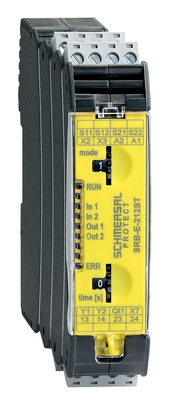
Immagine del prodotto (foto singola per catalogo)
Esempio di azionamento

Simbolo (standard tecnico)

103007222 SRB-E-212ST
- Plug-in screw terminals with coding
- STOP 0 / 1 Function
- 1 oder 2-channel control
- 2 safety contacts STOP 0
- 1 Safety output STOP 1
- Drop-out delay 0 … 30
| EU Declaration of Conformity |  |
| Original | K.A. Schmersal GmbH & Co. KG Möddinghofe 30 42279 Wuppertal Germany Internet: www.schmersal.com |
| Declaration: | We hereby certify that the hereafter described components both in their basic design and construction conform to the applicable European Directives. |
| Name of the component: | SRB211ST-24V V.2 SRB211ST/PC-24V V.2 SRB211ST/CC-24V V.2 |
| Description of the component: | Safety relay module for emergency stop circuits, guard door monitoring, magnetic safety switches and AOPD's |
| Relevant Directives: | Machinery Directive | 2006/42/EC |
| EMC-Directive | 2014/30/EU | |
| RoHS-Directive | 2011/65/EU |
| Applied standards: | DIN EN 60947-5-1:2018 DIN EN ISO 13849-1:2023 |
| Notified body for Type Examination: | DGUV Test Prüf- und Zertifizierungsstelle Elektrotechnik Gustav-Heinemann-Ufer 130 50968 Köln ID n°: 0340 |
| EC-Type Examination Certificate: | ET 24017 |
| Person authorised for the compilation of the technical documentation: | Oliver Wacker Möddinghofe 30 42279 Wuppertal |
| Place and date of issue: | Wuppertal, September 27, 2024 |
 |
| Authorised signature Philip Schmersal Managing Director |
Schmersal India Pvt. Ltd., Plot No - G-7/1, Ranjangaon MIDC, Tal. - Shirur, Dist.- Pune 412 220
I dettagli e i dati qui riportati sono stati attentamente verificati. Le immagini possono differire dagli originali. Altri dati tecnici possono essere trovati nei manuali. Salvo modifiche tecniche o errori.
Generato il 28/06/2025, 12:43