BNS 260-02/01ZG-ST-L
BNS 260-02/01ZG-ST-L
| Typebenaming van het product: BNS 260-(1)(2)Z(3)-(4)-(5) |
| (1) | |
| 11 | 1 maakcontact (NO) / 1 verbreekcontact (NC) |
| 02 | 2 verbreekcontacten (NC) |
| (2) | |
| zonder | zonder diagnoseuitgang |
| /01 | 1 verbreekcontact (NC) |
| (3) | |
| zonder | zonder LED-statusindicatie |
| G | met LED-statusindicatie |
| (4) | |
| zonder | Aansluitkabel |
| ST | met stekker |
| (5) | |
| L | Deur met aanslag links |
| R | deur met rechts zichtbare scharnieren |
- Aansluitstekker 8 mm, 6-polig, Vergrendeling met houdfunctie
- Kunststofbehuizing
- kleine bouwvorm
- Verdekte inbouw mogelijk
- 26 mm x 36 mm x 13 mm
- Lange levensduur
- geen mechanische slijtage
- Ongevoelig voor zijdelingse afwijking
- Ongevoelig voor vervuiling
Bestelvoorbeeld
| Typebenaming van het product |
BNS 260-02/01ZG-ST-L |
| Artikelnummer (bestelnummer) |
101184382 |
| EAN (Europees Artikel Nummer) |
4030661321813 |
| eCl@ss number, version 12.0 |
27-27-44-01 |
| eCl@ss number, version 11.0 |
27-27-24-02 |
| eCl@ss nummer, versie 9.0 |
27-27-24-02 |
| ETIM number, version 7.0 |
EC002544 |
| ETIM number, version 6.0 |
EC002544 |
Certificeringen - Voorschriften
|
cULus |
Algemene gegevens
| Voorschriften |
BG-GS-ET-14 EN IEC 60947-5-3 |
| Codeerniveau volgens EN ISO 14119 |
gering |
| Werkingsprincipe |
magnetisch |
| Inbouwcondities (mechanische) |
bijna vlak |
| Materiaal van de behuizing |
Kunststof, glasvezelversterkte thermoplast |
| Brutogewicht |
33 g |
Algemene gegevens - Eigenschappen
| Codering |
Ja |
| Geïntegreerde weergave, status |
Ja |
| Aantal verbreekcontacten |
3 |
| Aantal veiligheidscontacten |
2 |
Classificatie
| Normen, voorschriften: |
EN ISO 13849-1 |
| Gebruiksduur |
20 Jaar (Jaren) |
Veiligheidsclassificatie: - Veiligheidsuitgangen
| B10D Verbreekcontact (NG) |
25.000.000 schakelingen |
| B10D-waarde, verbreekcontact/maakcontact (NC/NO) |
25.000.000 schakelingen |
Mechanische gegevens
| Bedienelement |
Magneet |
| Deuraanslag |
Links |
| Bewegingsrichting |
Frontaal ten opzichte van de actieve zijde |
Mechanische gegevens - schakelafstanden volgens EN IEC 60947-5-3
| Opmerking (schakelafstand Sn) |
Axiale afwijking Een horizontale en verticale afwijking tussen de veiligheidssensor en de bediensleutel wordt getolereerd. De mogelijke afwijking is afhankelijk van de afstand tussen de actieve vlakken van de sensor en de bediensleutel. De sensor blijft actief in het tolerantiebereik. |
| Verzekerde inschakelafstand "IN" Sao |
5 mm |
| Verzekerde uitschakelafstand "UIT" Sar |
15 mm |
Mechanische gegevens - Aansluittechniek
| aansluitwijze |
Aansluitstekker 8 mm, 6-polig, vergrendeling met houdfunctie |
Mechanische gegevens - Afmetingen
| Lengte van de sensor |
13 mm |
| Breedte van de sensor |
26 mm |
| Hoogte van de sensor |
36 mm |
Omgevingsvoorwaarden
| Afdichtingsgraad |
IP67 |
| Ambient temperature |
-25 ... +70 °C |
| Storage and transport temperature |
-25 ... +70 °C |
| Trillingsvastheid volgens EN 60068-2-6 |
10…55 Hz, amplitude 1 mm |
| schokbestendig |
30 g / 11 ms |
Omgevingsvoorwaarden - Isolatieparameters
| Nominale isolatiespanning Ui |
75 VDC |
| Nominale impulsspanningsvastheid Uimp |
0,8 kV |
Elektrische gegevens
| Voorwaardelijke nominale kortsluitstroom volgens EN 60947-5-1 |
100 A |
| Schakelspanning, maximum |
24 VDC |
| Schakelstroom; maximum |
0,01 A |
| Schakelvermogen, maximum |
0,24 W |
| Schakelelement |
3 verbreekcontacten (NG) |
| Schakelfrequentie, maximum |
5 Hz |
Statusindicatie
| Opmerking (geïntegreerde weergave, status) |
LED licht op als de veiligheidsdeur gesloten is. |
Leveringsomvang
| Leveringsomvang |
Actuator must be ordered separately. |
Toebehoren
| Aanbeveling (bediensleutel) |
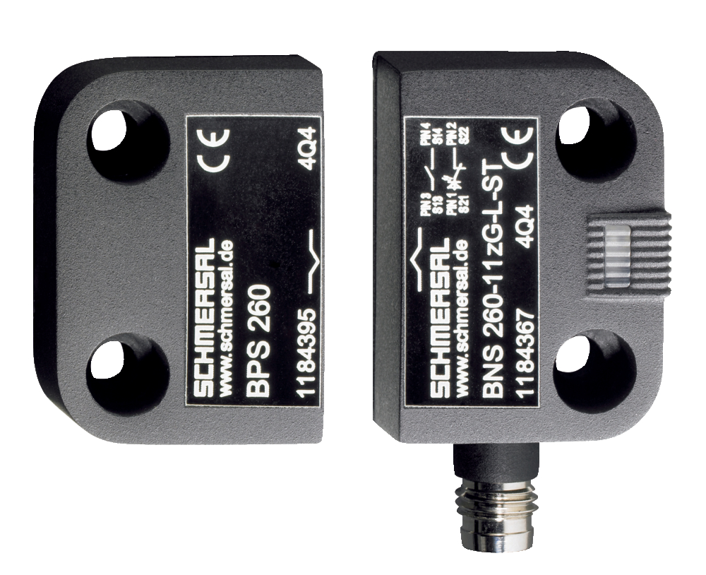
BPS 260 |
| Aanbeveling veiligheidsschakelcomponent |
SRB-E-301ST SRB-E-201LC |
Opmerking
| Opmerking (algemeen) |
De pinconfiguratie van de versies met geïntegreerde stekker wordt tussen haakjes weergegeven. |
Schakelvoorbeeld
| Opmerking (schakelvoorbeeld) |
De contacten S11-S12 en S21-S22 moeten in het veiligheidscircuit worden geïntegreerd. |
Taalfilter
Datasheet
Bedieningshandleiding en conformiteitsverklaring (Short)
UL-certificaat
SISTEMA-VDMA-bibliotheek/library
Download de nieuwste versie van Adobe Reader
Foto van het product (individuele catalogusfoto)
Maatschets basistoestel
Contactschema
Karakteristiek diagram

Karakteristiek diagram
Clipart

101184395 BPS 260-1
- Bedieningssleutel en sensor in hetzelfde bevestigingsvlak

101184396 BPS 260-2
- Bedieningssleutel "01#° dwars bevestigd ten opzichte van de sensor

101184643 SPACER BNS 260
- voor de montage van de veiligheidssensor en de bedienmagneet op ferromagnetisch materiaal

103007672 SRB-E-301ST
- Steekbare schroefklemmen met codering
- STOP 0 Functie
- 1 oder 2-kanalige aansturing
- Startknop / Autostart
- 1 Hulpcontact
- 3 veiligheidscontacten

103009970 SRB-E-201LC
- Steekbare schroefklemmen met codering
- STOP 0 Functie
- 1 oder 2-kanalige aansturing
- Startknop / Autostart
- 2 Veiligheidsuitgangen 2 A
- 1 Signaaluitgang

103009973 SRB-E-204ST
- Steekbare schroefklemmen met codering
- STOP 0 Functie
- Bewaking van 4 sensoren
- Startknop / Autostart
- 2 Veiligheidsuitgangen
- 4 Signaaluitgangen
101206010 A-K6P-M8-R-G-2M-GY-1-X-A-4
- Aansluitkabel
- 6-polig
- Vergrendeling met houdfunctie
101206011 A-K6P-M8-R-G-5M-GY-1-X-A-4
- Aansluitkabel
- 6-polig
- Vergrendeling met houdfunctie
101206012 A-K6P-M8-R-G-10M-GY-1-X-A-4
- Aansluitkabel
- 6-polig
- Vergrendeling met houdfunctie
101206013 A-K6P-M8-R-W-2M-GY-1-X-A-4
- M8, rond 8 mm
- Aansluitkabel
- 6-polig
- Vergrendeling met houdfunctie
101206014 A-K6P-M8-R-W-5M-GY-1-X-A-4
- M8, rond 8 mm
- Aansluitkabel
- 6-polig
- Vergrendeling met houdfunctie
101206015 A-K6P-M8-R-W-10M-GY-1-X-A-4
- Aansluitkabel
- 6-polig
- Vergrendeling met houdfunctie
Inhoudsopgave
- 1 About this document
- 1.1 Function
- 1.2 Target group of the operating instructions: authorised qualified personnel
- 1.3 Explanation of the symbols used
- 1.4 Appropriate use
- 1.5 General safety instructions
- 1.6 Warning about misuse
- 1.7 Exclusion of liability
- 2 Product description
- 2.1 Ordering code
- 2.2 Special versions
- 2.3 Purpose
- 2.4 Technical Data
- 3 Mounting
- 3.1 General mounting instructions
- 3.2 Dimensions
- 3.3 Axial misalignment
- 3.4 Adjustment
- 4 Electrical connection
- 4.1 General information for electrical connection
- 4.2 Contact Options
- 4.3 Connector accessories
- 5 Set-up and maintenance
- 6 Disassembly and disposal
- 6.1 Disassembly
- 6.2 Disposal
1 About this document
1.1 Function
This document provides all the information you need for the mounting, set-up and commissioning to ensure the safe operation and disassembly of the switchgear. The operating instructions enclosed with the device must always be kept in a legible condition and accessible.
1.2 Target group of the operating instructions: authorised qualified personnel
All operations described in the operating instructions manual must be carried out by trained specialist personnel, authorised by the plant operator only.
Please make sure that you have read and understood these operating instructions and that you know all applicable legislations regarding occupational safety and accident prevention prior to installation and putting the component into operation.
The machine builder must carefully select the harmonised standards to be complied with as well as other technical specifications for the selection, mounting and integration of the components.
The information contained in this operating instructions manual is provided without liability and is subject to technical modifications.
1.3 Explanation of the symbols used
- Information, hint, note: This symbol is used for identifying useful additional information.
- Caution: Failure to comply with this warning notice could lead to failures or malfunctions.
Warning: Failure to comply with this warning notice could lead to physical injury and/or damage to the machine.
1.4 Appropriate use
The Schmersal range of products is not intended for private consumers.
The products described in these operating instructions are developed to execute safety-related functions as part of an entire plant or machine. It is the responsibility of the manufacturer of a machine or plant to ensure the correct functionality of the entire machine or plant.
The safety switchgear must be exclusively used in accordance with the versions listed below or for the applications authorised by the manufacturer. Detailed information regarding the range of applications can be found in the chapter "Product description".
1.5 General safety instructions
The user must observe the safety instructions in this operating instructions manual, the country specific installation standards as well as all prevailing safety regulations and accident prevention rules.
- Further technical information can be found in the Schmersal catalogues or in the online catalogue on the Internet: products.schmersal.com.
1.6 Warning about misuse
- In case of improper use or manipulation of the safety switchgear, personal hazards or damages to machinery or plant components cannot be excluded. There are no residual risks, provided that the safety instructions as well as the instructions regarding mounting, commissioning, operation and maintenance are observed.
1.7 Exclusion of liability
We shall accept no liability for damages and malfunctions resulting from defective mounting or failure to comply with the operating instructions manual. The manufacturer shall accept no liability for damages resulting from the use of unauthorised spare parts or accessories.
For safety reasons, invasive work on the device as well as arbitrary repairs, conversions and modifications to the device are strictly forbidden, the manufacturer shall accept no liability for damages resulting from such invasive work, arbitrary repairs, conversions and/or modifications to the device.
2 Product description
2.1 Ordering code
| Product type description: BNS 260-(1)(2)Z(3)-(4)-(5) |
| (1) | |
| 11 | 1 NO contact/1 NC contact |
| 02 | 2 NC contact |
| (2) | |
| without | with diagnostic output |
| /01 | 1 NC contact |
| (3) | |
| without | without LED switching conditions display |
| G | with LED switching conditions display |
| (4) | |
| without | Pre-wired cable |
| ST | with connector |
| (5) | |
| L | Door hinge on left-hand side |
| R | Door hinge on right-hand side |
2.2 Special versions
For special versions, which are not listed in the ordering code, these specifications apply accordingly, provided that they correspond to the standard version.
2.3 Purpose
The safety sensor BNS 260 is designed to monitor the position of movable safetey guards in safety circuits to EN ISO 14119 and EN 60947-5-3. To actuate the safety sensors, only the BPS 260-1 or BPS 260-2 actuators can be used.
The safety switches are used for applications, in which the hazardous situation is terminated without delay when the safety guard is opened.
- The safety switchgears are classified according to EN ISO 14119 as type 4 interlocking devices.
Only the entire system consisting of the BNS 260 safety sensor and the BPS 260-1 or BPS 260-2 actuator and the safety-monitoring module (SRB) meets the requirements of the standard EN 60947-5-3.
- The user must evaluate and design the safety chain in accordance with the relevant standards and the required safety level.
- The entire concept of the control system, in which the safety component is integrated, must be validated to the relevant standards.
2.4 Technical Data
Certificeringen - Voorschriften
|
cULus |
Algemene gegevens
| Voorschriften |
BG-GS-ET-14 EN IEC 60947-5-3 |
| Codeerniveau volgens EN ISO 14119 |
gering |
| Werkingsprincipe |
magnetisch |
| Inbouwcondities (mechanische) |
bijna vlak |
| Materiaal van de behuizing |
Kunststof, glasvezelversterkte thermoplast |
| Brutogewicht |
33 g |
Algemene gegevens - Eigenschappen
| Codering |
Ja |
| Geïntegreerde weergave, status |
Ja |
| Aantal verbreekcontacten |
3 |
| Aantal veiligheidscontacten |
2 |
Classificatie
| Normen, voorschriften: |
EN ISO 13849-1 |
| Gebruiksduur |
20 Jaar (Jaren) |
Veiligheidsclassificatie: - Veiligheidsuitgangen
| B10D Verbreekcontact (NG) |
25.000.000 schakelingen |
| B10D-waarde, verbreekcontact/maakcontact (NC/NO) |
25.000.000 schakelingen |
Mechanische gegevens
| Bedienelement |
Magneet |
| Deuraanslag |
Links |
| Bewegingsrichting |
Frontaal ten opzichte van de actieve zijde |
Mechanische gegevens - schakelafstanden volgens EN IEC 60947-5-3
| Opmerking (schakelafstand Sn) |
Axiale afwijking Een horizontale en verticale afwijking tussen de veiligheidssensor en de bediensleutel wordt getolereerd. De mogelijke afwijking is afhankelijk van de afstand tussen de actieve vlakken van de sensor en de bediensleutel. De sensor blijft actief in het tolerantiebereik. |
| Verzekerde inschakelafstand "IN" Sao |
5 mm |
| Verzekerde uitschakelafstand "UIT" Sar |
15 mm |
Mechanische gegevens - Aansluittechniek
| aansluitwijze |
Aansluitstekker 8 mm, 6-polig, vergrendeling met houdfunctie |
Mechanische gegevens - Afmetingen
| Lengte van de sensor |
13 mm |
| Breedte van de sensor |
26 mm |
| Hoogte van de sensor |
36 mm |
Omgevingsvoorwaarden
| Afdichtingsgraad |
IP67 |
| Ambient temperature |
-25 ... +70 °C |
| Storage and transport temperature |
-25 ... +70 °C |
| Trillingsvastheid volgens EN 60068-2-6 |
10…55 Hz, amplitude 1 mm |
| schokbestendig |
30 g / 11 ms |
Omgevingsvoorwaarden - Isolatieparameters
| Nominale isolatiespanning Ui |
75 VDC |
| Nominale impulsspanningsvastheid Uimp |
0,8 kV |
Elektrische gegevens
| Voorwaardelijke nominale kortsluitstroom volgens EN 60947-5-1 |
100 A |
| Schakelspanning, maximum |
24 VDC |
| Schakelstroom; maximum |
0,01 A |
| Schakelvermogen, maximum |
0,24 W |
| Schakelelement |
3 verbreekcontacten (NG) |
| Schakelfrequentie, maximum |
5 Hz |
Statusindicatie
| Opmerking (geïntegreerde weergave, status) |
LED licht op als de veiligheidsdeur gesloten is. |
Schakelvoorbeeld
| Opmerking (schakelvoorbeeld) |
De contacten S11-S12 en S21-S22 moeten in het veiligheidscircuit worden geïntegreerd. |
Note about the safety classification
For 2-channel use with suitable logic, can be used up to Cat. 4 / PL e.

(Determined values can vary depending on the application-specific parameters hop, dop and tcycle as well as the load.)
If multiple safety components are wired in series, the Performance Level to EN ISO 13849-1 will be reduced due to the restricted error detection under certain circumstances.
UL notice
- For use in NFPA 79 Applications. Adapters providing field wiring means are available from the manufacturer. Refer to manufacturers information.
3 Mounting
3.1 General mounting instructions
- During fitting, the requirements of EN ISO 14119 must be observed.
- Fitting is only authorised in a de-energised condition
- Do not use the sensor and the actuator as a mechanical backstop
- Any mounting position, provided that the active surfaces are opposite
- Do not subject the safety sensor and actuator to extreme vibrations and shocks
To avoid any interference inherent to this kind of system and any reduction of the switching distances, please observe the following guidelines:
- Ensure the safety sensor is mounted on a flat surface
- Do not install the safety sensor and the actuator in strong magnetic fields
- If possible, do not mount the sensor and the actuator on ferromagnetic material. A non-magnetic spacer of at least 5 mm thick or the original spacer must be used. The use of non-magnetic fixing screws is recommended also.
- Keep away from metal chips
- The mounting distance between two sensors should always be at least 50 mm
- The actuator must be permanently fitted to the safety guards and protected against displacement by suitable measures (tamperproof screws, gluing, drilling of the screw heads).
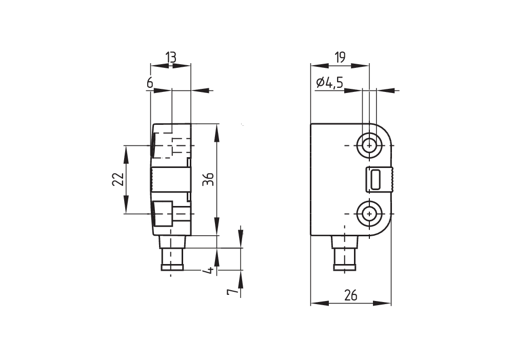
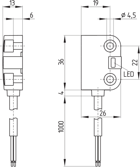
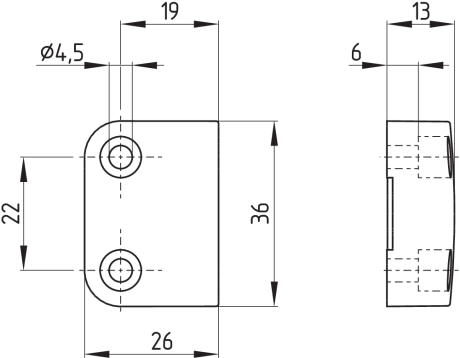
3.2 Dimensions
All measurements in mm.
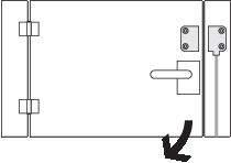
Sensor with connector, right hinged door
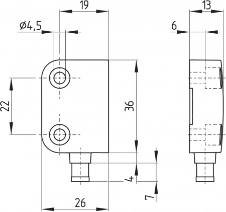
Safety sensor with cable, left hinged door
Actuator
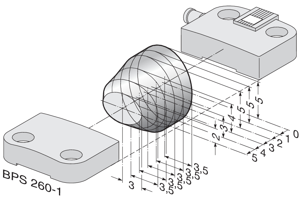
3.3 Axial misalignment
A horizontal and vertical misalignment of the safety sensor and the actuator is tolerated. The possible misalignment depends on the distance of the active surfaces of the sensor and the actuator. The sensor remains active within the tolerance range.
The specified switching distances refer to opposedly mounted safety sensors and actuators.

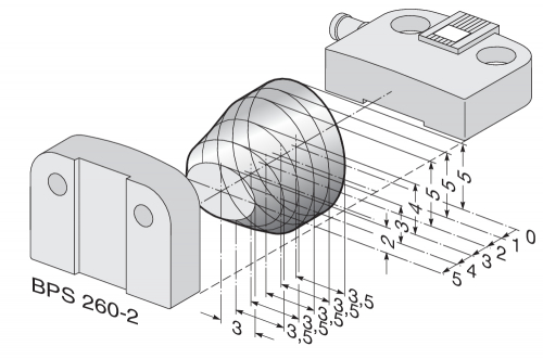
| Assured switching distance: | sao | = | 5 mm 8 mm (ordering suffix -2750) |
| Assured switch-off distance: | sar | = | 15 mm 18 mm (ordering suffix -2750) |
3.4 Adjustment
- Recommended Adjustment
Align the safety sensor and actuator at a distance of 0.5 x sao.
Align the central markings of the safety sensor and the actuator with each other. The LED can only be used as rough setting tool. The correct functionality of both safety channels must be checked by means of the connected safety-monitoring module.
4 Electrical connection
4.1 General information for electrical connection
- The electrical connection may only be carried out by authorised personnel in a de-energised condition.
Connecting multiple safety sensors to one SRB safety-monitoring module is technically possible. To connect multiple safety sensors (check if authorised!), their NO contacts are wired in parallel and their NC contacts in series. The Protect-IE-11 or -02 or PROTECT-PE-11 (-AN) or -02 input expander module can be used to connect up to 4 safety sensors with NC/NC or NC/NO contacts.
Safety sensors equipped with LED's shall not be wired in series, except for the PROTECT-IE or PROTECT-PE input expander module. As a result of this, the luminosity of the LEDs would considerably decrease and the voltage could drop below the minimum input voltage of the downstream safety-monitoring module.
- Information for the selection of suitable safety-monitoring modules can be found in the Schmersal catalogues or in the online catalogue on the Internet: products.schmersal.com
4.2 Contact Options
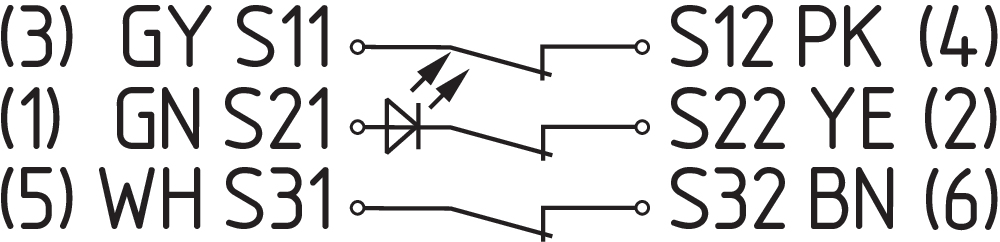
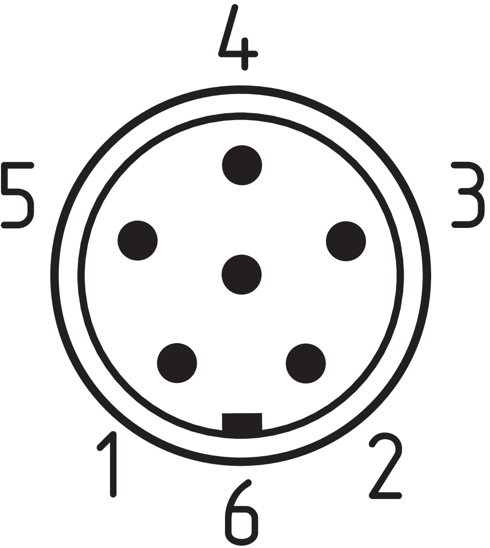
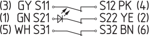
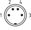
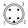
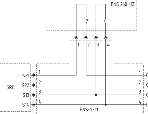
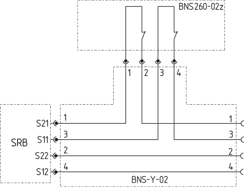
The safety sensors must be wired in accordance with the wire colours or the pin configuration.
The contact position shows the actuated sensor function when the safety guard is closed. For safety sensors with LED, the LED is illuminated when the safety guard is closed. The contact configurations of the versions with or without LED are identical.
| Safety contacts: | S21-S22 and S11-S12 or S13-S14 |
| Signalling contact: | S31-S32 |
The numbers between brackets indicate the PIN configuration of the versions with connector plug or connecting cable with connector; indication of the wire colours for the version with cable.
| BNS 260-02Z(G) | BNS 260-11Z(G) |
|---|---|
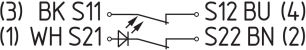 | 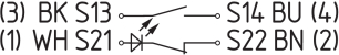 |
| BNS 260-02/01Z(G) | BNS 260-11/01Z(G) |
|---|---|
 | 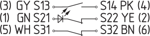 |
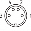
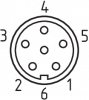
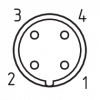
4.3 Connector accessories
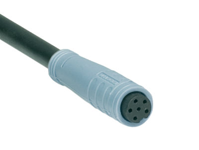
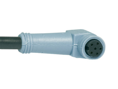
| Connector plug or cable connector | ||
|---|---|---|
 |  |  |
| M8, 4-pole, with screw terminal or snap fitting | 8 mm, 6-pole, with snap fitting | M12, 4-pole, screw connection with vibration safeguard |
Accessories: connecting cable with coupling
| M8, 4-pole, with screw terminal | 2 m | 5 m | 10 m | |||
|---|---|---|---|---|---|---|
 | 1 | BN | straight | 103011340 | 103007356 | - |
| 2 | WH | |||||
| 3 | BU | angled | 101210557 | 101210559 | - | |
| 4 | BK | |||||
| 8 mm, 6-pole, with snap fitting | 2 m | 5 m | 10 m | |||
|---|---|---|---|---|---|---|
 | 1 | GN | straight | 101206010 | 101206011 | 101206012 |
| 2 | YE | |||||
| 3 | GY | |||||
| 4 | PK | angled | 101206013 | 101206014 | 101206015 | |
| 5 | WH | |||||
| 6 | BN | |||||
| M12, 4-pole, with screw terminal | 2 m | 5 m | 10 m | |||
|---|---|---|---|---|---|---|
 | 1 | BN | Straight | 103010891 | 103010892 | 103010893 |
| 2 | WH | |||||
| 3 | BU | |||||
| 4 | BK | |||||
Accessory: Y-adapter BNS-Y-11
Accessory: Y-adapter BNS-Y-02
5 Set-up and maintenance
The safety function of the safety components must be tested. In the case of correct installation and adequate use, the safety switchgear features maintenance-free functionality. A regular visual inspection and functional test, including the following steps, is recommended:
- Check fixation of the safety switch and the actuator.
- Fitting and integrity of the cable connections.
- The system is free of dirt and soiling (in particular metal chips).
- Adequate measures must be taken to ensure protection against tampering either to prevent tampering of the safety guard, for instance by means of replacement actuators.
- Damaged or defective components must be replaced.
6 Disassembly and disposal
6.1 Disassembly
The safety switchgear must be disassembled in a de-energised condition only.
6.2 Disposal
- The safety switchgear must be disposed of in an appropriate manner in accordance with the national prescriptions and legislations.
| EU-conformiteitsverklaring |  |
| Original | K.A. Schmersal GmbH & Co. KG Möddinghofe 30 42279 Wuppertal Germany Internet: www.schmersal.com |
| Verklaring: | Hiermee verklaren wij dat de hieronder beschreven producten op grond van hun ontwerp en constructie beantwoorden aan de relevante Europese Richtlijnen. |
| Benaming van de component: | BNS 260 |
| Type: | zie bestelsleutel |
| Beschrijving van de component: | Gecodeerde veiligheidssensor met magnetisch werkingsprincipe in combinatie met de Schmersal veiligheidsmodules SRB(-E) / PROTECT-SELECT / PSC1 of een vergelijkbare veiligheidsgerichte besturing die aan de vereisten van de EN 60947-5-3 beantwoordt. |
| Geharmoniseerde Richtlijnen: | Machinerichtlijn | 2006/42/EG | |
| RoHS-Richtlijn | 2011/65/EU |
| Toegepaste normen: | EN 60947-5-3:2013 EN ISO 14119:2013 |
| Gemachtigde voor het samenstellen van de technische documentatie: | Oliver Wacker Möddinghofe 30 42279 Wuppertal |
| Plaats en datum van opstelling: | Wuppertal, 28. januari 2022 |
 |
| Rechtsgeldige handtekening Philip Schmersal Directeur |
| UK Declaration of Conformity | |
| Company: | K.A. Schmersal GmbH & Co. KG Möddinghofe 30 42279 Wuppertal Germany Internet: www.schmersal.com |
| Declaration: | We hereby, under sole responsibility, certify that the hereafter described components both in their basic design and construction conform to the relevant statutory requirements, regulations and designated standards of the United Kingdom. |
| Name of the component: | BNS 260 |
| Type: | See ordering code |
| Description of the component: | Coded safety-sensor with magnetic operating principle in combination with the SRB(-E) / PROTECT-SELECT / PSC1 safety-monitoring modules from Schmersal or an equivalent safety-oriented control system fulfilling the requirements of the EN 60947-5-3. |
| Relevant legislation: | Supply of Machinery (Safety) Regulations | 2008 |
| The Restriction of the Use of Certain Hazardous Substances in Electrical and Electronic Equipment Regulations | 2012 |
| Designated standards: | EN 60947-5-3:2013 EN ISO 14119:2013 |
| UK-Importer / Person authorised for the compilation of the technical documentation: | Schmersal UK Ltd. Paul Kenney Unit 1, Sparrowhawk Close Enigma Business Park Malvern, Worcestershire, WR14 1GL |
| Place and date of issue: | Wuppertal, June 17, 2022 |
|
| Authorised signature Philip Schmersal Managing Director |
Schmersal Nederland B.V., Lorentzstraat 31, 3846 AV Harderwijk
De genoemde gegevens en informatie zijn zorgvuldig gecontroleerd. Afbeeldingen kunnen afwijken van het origineel. Verdere technische gegevens zijn te vinden in de handleiding. Technische wijzigingen en fouten voorbehouden.
Gegenereerd op 30-12-2024 03:23