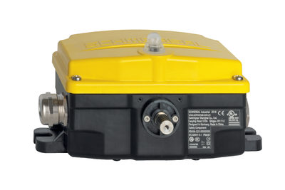
AES2285

AES2285
- Multi-evaluation of up to 6 safety guards
- Monitoring of BNS range magnetic safety sensors
- 2 safety contacts, STOP 0
- 6 Signalling outputs
- Additional contacts by means of output expander
- Individual signal outputs for each guard door
Ordering data
| Note (Delivery capacity) |
Phased-out product |
| Product type description |
AES2285 |
| Article number (order number) |
101172211 |
| EAN (European Article Number) |
4250116201846 |
| eCl@ss number, version 12.0 |
27-37-18-19 |
| eCl@ss number, version 11.0 |
27-37-18-19 |
| eCl@ss number, version 9.0 |
27-37-18-19 |
| ETIM number, version 7.0 |
EC001449 |
| ETIM number, version 6.0 |
EC001449 |
| Notice |
Utgått produkt |
General data
| Standards |
BG-GS-ET-14 BG-GS-ET-20 EN IEC 62061 EN ISO 13849-1 EN IEC 60947-5-1 EN IEC 60947-5-3 EN IEC 60947-5-5 EN IEC 61508 EN IEC 60204-1 EN IEC 60947-1 |
| Climatic stress |
EN 60068-2-78 |
| Housing material |
Plast, glassfiber forsterket termoplast, ventilert |
| Gross weight |
430 g |
General data - Features
| Electronic Fuse |
Ja |
| Wire breakage detection |
Ja |
| Cross-circuit detection |
Ja |
| Removable Terminals |
Ja |
| Start input |
Ja |
| Feedback circuit |
Ja |
| Automatic reset function |
Ja |
| Reset edge detection |
Ja |
| Reset after disconnection of supply voltage |
Ja |
| Earth connection detection |
Ja |
| Integral system diagnostics, status |
Ja |
| Number of auxiliary contacts |
1 |
| Number of LEDs |
3 |
| Number of undelayed semi-conductor outputs with signaling function |
6 |
| Number of safety contacts |
2 |
| Number of Snap-in contacts, maximum |
6 |
| Number of Snap-in contacts, minimum |
1 |
| Number of signalling outputs |
6 |
| Safety classification |
| Vorschriften |
EN IEC 60947-5-1 EN IEC 61508 |
| Stop-Category |
0 |
| Safety classification - Relay outputs |
| Performance Level, up to |
d |
| Category |
3 |
| Diagnostic Coverage (DC) Level |
≥ 99 % |
| PFH value |
2,00 x 10⁻⁸ /h |
| Safety Integrity Level (SIL), suitable for applications in |
3 |
| Mission time |
20 Year(s) |
| Common Cause Failure (CCF), minimum |
65 |
Mechanical data
| Mechanical life, minimum |
10.000.000 Operations |
| Mounting |
kneppes inn på standard DIN-skinne iht. EN 60715 |
Mechanical data - Connection technique
| Terminal designations |
IEC/EN 60947-1 |
| Termination |
Stiv eller fleksibel Skrueforbindelse M20 x 1.5 |
| Cable section, minimum |
0,25 mm² |
| Cable section, maximum |
2,5 mm² |
| Tightening torque of Clips |
0,6 Nm |
Mechanical data - Dimensions
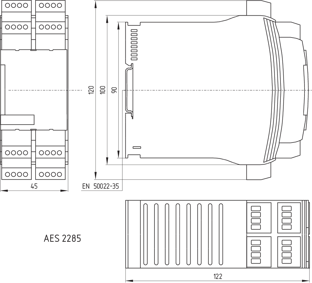
| Width |
45 mm |
| Height |
100 mm |
| Depth |
121 mm |
Ambient conditions
| Degree of protection of the enclosure |
IP40 |
| Degree of protection of the mounting space |
IP54 |
| Degree of protection of clips or terminals |
IP20 |
| Ambient temperature |
-25 ... +45 °C |
| Storage and transport temperature |
-40 ... +85 °C |
| Resistance to vibrations |
10 ... 55 Hz, Amplitude 0,35 mm |
| Restistance to shock |
10 g / 11 ms |
Ambient conditions - Insulation values
| Rated impulse withstand voltage Uimp |
4 kV |
| Overvoltage category |
III |
| Degree of pollution |
2 |
Electrical data
| Frequency range |
50 Hz 60 Hz |
| Operating voltage |
24 VAC -15 % / +10 % |
| Ripple voltage |
10 % |
| Thermal test current |
6 A |
| Rated operating voltage |
24 VAC |
| Rated operating voltage |
24 VDC |
| Rated AC voltage for controls, 50 Hz, minimum |
20,4 VAC |
| Rated control voltage at AC 50 Hz, maximum |
26,4 VAC |
| Rated AC voltage for controls, 60 Hz, minimum |
20,4 VAC |
| Rated control voltage at AC 60 Hz, maximum |
26,4 VAC |
| Rated AC voltage for controls at DC minimum |
20,4 VDC |
| Rated control voltage at DC, maximum |
28,8 VDC |
| Electrical power consumption |
3,6 W |
| Electrical power consumption |
6,6 VA |
| Contact resistance, maximum |
0,1 Ω |
| Note (Contact resistance) |
I ny tilstand |
| Drop-out delay in case of power failure, typically |
80 ms |
| Drop-out delay in case of emergency, typically |
20 ms |
| Pull-in delay at automatic start, maximum, typically |
100 ms |
| Pull-in delay at RESET, typically |
20 ms |
| Material of the contacts, electrical |
AgCdO, selvrensende, positiv handling |
Electrical data - Safe relay outputs
| Voltage, Utilisation category AC-15 |
230 VAC |
| Current, Utilisation category AC-15 |
6 A |
| Voltage, Utilisation category DC-13 |
24 VDC |
| Current, Utilisation category DC-13 |
6 A |
| Switching capacity, minimum |
10 VDC |
| Switching capacity, minimum |
10 mA |
| Switching capacity, maximum |
250 VAC |
| Switching capacity, maximum |
8 A |
Electrical data - Digital inputs
| Conduction resistance, maximum |
40 Ω |
Electrical data - Digital Output
| Voltage, Utilisation category DC-12 |
24 VDC |
| Current, Utilisation category DC-12 |
0,1 A |
Electrical data - Relay outputs (auxiliary contacts)
| Switching capacity, maximum |
24 VDC |
| Switching capacity, maximum |
2 A |
Electrical data - Electromagnetic compatibility (EMC)
| EMC rating |
EMC-Directive |
Status indication
| Indicated operating states |
Posisjon relé K2 Posisjon relé K1 Intern driftsspenning Ui |
Other data
| Note (applications) |
Sikkerhetssensor sikkerhetsinnretning |
Note
| Note (General) |
Induktive belastninger (f.eks. kontaktorer, reléer, etc.) må undertrykkes ved hjelp av en egnet krets. |
Wiring example
| Note (Wiring diagram) |
Kablingsskjemaet vises med vernedørene lukket og i de-energisert tilstand. Tilbakemeldingskretsen overvåker posisjonen for kontaktorene K3 og K4. Automatisk start: Automatisk start programmeres ved å koble tilbakemeldingskretsen til terminalene X1/X3 Dersom tilbakemeldingskrets ikke er nødvendig, etabler en bro Å sikre 6 vaktdører opp til PL d og kategori 3 Overvåking av 6 vernedør(er), hver med en magnetisk sikkerhetssensor i BNS-serien Startknapp (S) med kantdetektering |
Språk filter
Datablad
Bruksanvisning og konformitetserklæring
kablingseksempel (elektr. kabling)
Kraft - vei diagram
SISTEMA-VDMA Bibliotek/Library
Last ned den nyeste versjonen av Adobe Reader
Produktbilde (enkelt katalogbilde)
Dimensjonsriktig tegning grunnenhet
kablingseksempel

Symbol (teknisk standard)


103009973 SRB-E-204ST
- Plug-in screw terminals with coding
- STOP 0 Function
- Monitoring of 4 sensors
- Start button / Auto-start
- 2 Safety outputs
- 4 Signalling outputs

103009970 SRB-E-201LC
- Plug-in screw terminals with coding
- STOP 0 Function
- 1 oder 2-channel control
- Start button / Auto-start
- 2 Safety outputs 2 A
- 1 Signalling output

103007672 SRB-E-301ST
- Plug-in screw terminals with coding
- STOP 0 Function
- 1 oder 2-channel control
- Start button / Auto-start
- 1 Auxiliary contact
- 3 safety contacts
| EU Declaration of Conformity |  |
| Original | K.A. Schmersal GmbH & Co. KG Möddinghofe 30 42279 Wuppertal Germany Internet: www.schmersal.com |
| Declaration: | We hereby certify that the hereafter described components both in their basic design and construction conform to the applicable European Directives. |
| Name of the component: | AES2285 |
| Description of the component: | Safety-monitoring module for emergency stop circuits, guard door monitoring and magnetic safety switches |
| Relevant Directives: | Machinery Directive | 2006/42/EC |
| EMC-Directive | 2014/30/EU | |
| RoHS-Directive | 2011/65/EU |
| Applied standards: | EN 60947-5-1:2017 EN ISO 13849-1:2015 EN ISO 13849-2:2012 |
| Notified body, which approved the full quality assurance system, referred to in Appendix X, 2006/42/EC: | TÜV Rheinland Industrie Service GmbH Am Grauen Stein, 51105 Köln ID n°: 0035 |
| Person authorised for the compilation of the technical documentation: | Oliver Wacker Möddinghofe 30 42279 Wuppertal |
| Place and date of issue: | Wuppertal, February 25, 2021 |
 |
| Authorised signature Philip Schmersal Managing Director |
Schmersal India Pvt. Ltd., Plot No - G-7/1, Ranjangaon MIDC, Tal. - Shirur, Dist.- Pune 412 220
Data og verdier er kontrollert omhyggelig. Bilder kan avvike fra originalen. Ytterligere tekniske data finner du i manualen. Tekniske modifiseringer og feil kan forkomme.
Generert til 23.06.2025, 21:16
Nylig sett