SLG445-ER-0500-02-01
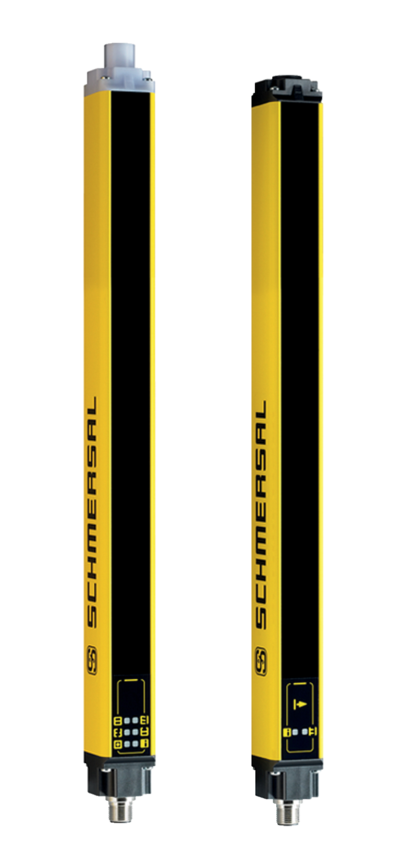
SLG445-ER-0500-02-01
| Produkt-Typbezeichnung: SLG445-ER-(1)-(2) |
| (1) | |
| 0500-02 | Abstand der äußersten Strahlen 500 mm, 2-strahlig |
| 0800-03 | Abstand der äußersten Strahlen 800 mm, 3-strahlig |
| 0900-04 | Abstand der äußersten Strahlen 900 mm, 4-strahlig |
| (2) | |
| 01 | Integrierte Statusleuchte, Reichweite 0,3 ... 12 m |
| H1 | Integrierte Statusleuchte, Reichweite 3 ... 20 m |
- Safety type 4 in accordance with IEC 61496-1
- User-friendly parameter setting, no tools required
- Reliable safety concept in case of interferences (EMC, welding sparks)
- Process safety with highest availability
- active integrated set-up tool
- Multifunctional
Ordering data
| Product type description |
SLG445-ER-0500-02-01 |
| Article number (order number) |
103005424 |
| EAN (European Article Number) |
4030661436388 |
| eCl@ss number, version 12.0 |
27-27-27-03 |
| eCl@ss number, version 11.0 |
27-27-27-03 |
| eCl@ss number, version 9.0 |
27-27-27-03 |
| ETIM number, version 7.0 |
EC001832 |
| ETIM number, version 6.0 |
EC001832 |
Approvals - Standards
| Certificates |
cULus |
General data
| Standards |
CLC/TS 61496-2 EN IEC 61496-2 EN IEC 61496-1 |
| Note (Software Version) |
ab 2024 Version 1.0 |
| Housing material |
Aluminium |
| Reaction time, maximum |
10 ms |
| Gross weight |
980 g |
| Radiation emission level to EN 12198-1 |
Kategorie 0 |
| Risk group classification of lamp systems to EN 62471 |
Freie Gruppe |
General data - Features
| Muting function |
Ja |
| Override |
Ja |
| Clock control possible |
Ja |
| Restart interlock (manual reset) |
Ja |
| Beam coding available |
Ja |
| 7-segment display |
Ja |
| Integral system diagnostics, status |
Ja |
| Integral system diagnostics |
Ja |
| Number of fail-safe digital outputs |
2 |
| Number of beams |
2 |
| Safety classification |
| Vorschriften |
EN ISO 13849-1 EN IEC 62061 |
| Performance Level, up to |
e |
| Category |
4 |
| PFH value |
5,14 x 10⁻⁹ /h |
| Safety Integrity Level (SIL), suitable for applications in |
3 |
| Mission time |
20 Year(s) |
| Safety type in accordance with IEC 61496-1 |
4 |
Mechanical data
| Detection ability for test bodies at v = 1.6 m/s |
500 mm |
| Height of the protection field |
500 mm |
| Range, protection field, minimum |
0,3 m |
| Range, protection field, maximum |
12 m |
| Note |
Reduzierung der Reichweite um 10 % bei einer Umgebungstemperatur von -25°C |
| Wave length of the laserdiode |
880 nm |
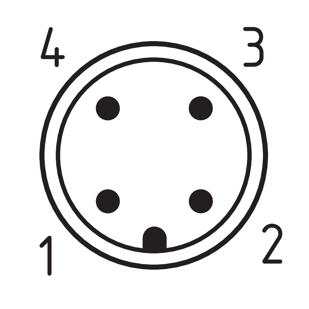
Mechanical data - Connection technique
| Length of cable |
100 m |
| Termination |
Steckverbinder |
| Terminal connector, Recipient |
Einbaustecker M12, 12-polig |
| Terminal, Connector, Transmitter |
Einbaustecker M12, 4-polig |
| Terminal (mechanical) |
mit Metallgewinde |
Mechanical data - Dimensions
| Length of sensor |
33 mm |
| Width of sensor |
27,8 mm |
| Height of the Sensor (Receiver) |
621 mm |
| Height of the Sensor (Transmitter) |
611 mm |
Ambient conditions
| Degree of protection |
IP67 |
| Ambient temperature |
-25 ... +50 °C |
| Storage and transport temperature |
-25 ... +70 °C |
| Resistance to vibrations |
10 … 55 Hz |
| Restistance to shock |
10 g, 16 ms, nach EN 60028-2-29 |
| Protection class |
III |
Electrical data
| Operating voltage |
24 VDC -10 % / +10 % ((PELV) Netzgerät Imax 2,0 A, gemäß EN 60204 (Netzausfall ≤ 20 ms)) |
|
| Rated operating voltage |
24 VDC |
|
| Length of cable, maximum |
100 m |
|
| Rated operating current, Emitter |
200 mA |
|
|
700 mA |
| Switching thresholds |
11 … 30 V (HIGH) 0 … 2 V (LOW) |
Electrical data - Power supply external devices
| Designation, Power supply |
ML |
| Rated operating voltage |
24 VDC |
| Rated operating current |
250 mA |
Electrical data - Control inputs
| Designation, Control inputs |
S1, S2, MSG 1 und MSG 2 |
| Current consumption |
3 … 10 mA (HIGH) 0 … 2 mA (LOW) |
| Actuation time for manual start |
50 … 1500 ms |
| Note |
Signalübernahme mit fallender Flanke |
Electrical data - Control inputs EDM
| Designation, Contactor controls EDM (Feedback circuits) |
D_IN |
| Switching thresholds |
11 … 30 V (HIGH) 0 … 2 V (LOW) |
| Current consumption |
3 … 10 mA (HIGH) 0 … 2 mA (LOW) |
| Reaction time of the external devices, maximum |
500 ms |
Electrical data - Safety digital outputs
| Designation, Safety outputs |
OSSD 1 und OSSD 2 |
| Output current, (fail-safe output), maximum |
0,25 A |
| Design of control elements |
OSSD, kurzschlussfest, p-schaltend |
| Leakage current Ir, maximum |
1 mA |
| Test pulse interval, typical |
750 ms |
| Test pulse duration, maximum |
0,1 ms |
| Classification ZVEI CB24I, Source |
C3 |
| Classification ZVEI CB24I, Sink |
C1 C2 C3 |
| Load capacity, maximum |
2,2 µF |
| Load inductance, maximum |
2 H |
| Note |
Lastinduktivität erzeugt beim Abschalten eine induzierte Spannung, welche nachgeschaltete Bauelemente gefährden (Funkenlöschglied). |
| Switching voltage |
15 … 26,4 V (HIGH) 0 … 2 V (LOW) |
| Note |
Gemäß EN 61131-2 |
| Note |
Im Fehlerfall fließt maximal der Leckstrom in der OSSD Leitung. Das nachgeschaltete Steuerelement muss diesen Zustand als LOW erkennen. Eine sichere SPS muss diesen Zustand erkennen. |
| Conduction resistance, maximum |
2,5 Ω |
LED status display - LED 01
| LED status |
OSSD EIN, OSSD AUS, Wiederanlauf, Signalempfang, Ausblendung, Information |
| LED position |
Empfänger |
LED status display - LED 02
| LED status |
Senden und Status |
| LED position |
Sender |
Other data
| Note (applications) |
Automatikbetrieb, Wiederanlaufsperre, doppelte Quittierung, Schützkontrolle, Ausblendung von Objekten (ortsunveränderlich und ortsveränderlich), alternative Strahlkodierung, Muting, Takt, Mehrfachabtastung |
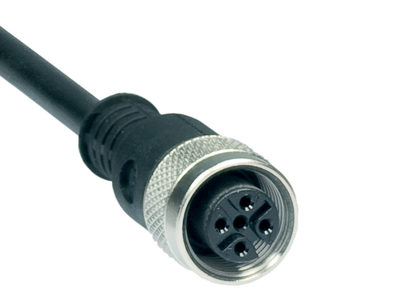
Pin assignment
| Connection |
Empfänger |
| PIN 1 |
24 VDC Spannungsversorgung |
| PIN 2 |
0 VDC Spannungsversorgung |
| PIN 3 |
Freigabe S1 Eingang Freigabe S1 |
| PIN 4 |
OSSD 1 Sicherheitsausgang 1 |
| PIN 5 |
D_OUT Betriebsart |
| PIN 6 |
OSSD 2 Sicherheitsausgang 2 |
| PIN 7 |
Mutingbetrieb: ML Muting-Leuchte |
| PIN 8 |
Freigabe S2 Eingang Freigabe S2 |
| PIN 9 |
Mutingbetrieb: D_IN Eingang EDM, Bandstopp, Muting Enable |
| PIN 10 |
Mutingbetrieb: MSG 2 Schalteingang Muting-Sensor-Gruppe MSG 2 |
| PIN 11 |
Nicht belegt |
| PIN 12 |
Mutingbetrieb: MSG 1 Schalteingang Muting-Sensor-Gruppe MSG 1 |
| Connection |
Sender |
| PIN 1 |
24 VDC Spannungsversorgung |
| PIN 2 |
COD1 Kodierung 1 |
| PIN 3 |
0 VDC Spannungsversorgung |
| PIN 4 |
COD2 Kodierung 2 |
Scope of delivery
| Scope of delivery |
Sender + Empfänger, Befestigungsset |
Accessory
| Recommended safety switchgear |
SRB-E 301 |
Sprachfilter
Datenblatt
Betriebsanleitung und Konformitätserklärung
UL-Zertifikat
Broschüre
SISTEMA-VDMA Bibliothek/Library
Download der aktuellen Version von Adobe Reader
Produktbild (Katalogeinzelphoto )
Polbild


101216833 MS-1100
- Kit with 4 mounting angles
- for SLC/SLG 440, SLC/SLG440COM, SLC/SLG445
103000081 MS-1102
- Kit with 4 mounting angles
- Stainless steel (V4A)
- for SLC/SLG 440, SLC/SLG440COM, SLC/SLG445

101216834 MS-1110
- mounting kit for central fixation
- Kit with 2 mounting angles
- for SLC/SLG 440, SLC/SLG440COM, SLC/SLG445
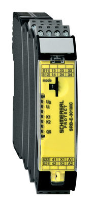
103014374 SRB-E-301MC
- 1 Signalling contact
- Plug-in screw terminals with coding
- Suitable for applications up to Cat. 4 / PL e und up to SIL 3
- 1 or 2 channel signal evaluation
- Start / feedback circuit monitoring
- Optionally with short-circuit recognition
- 3 safety contacts, stop category 0

103006073 MUT-SET-L-01
- Plug and play solution for muting applications
- Reduced mounting and wiring times
- Easy wiring with MCU-02 only one cable to the control cabinet
- One part number for all components
- Muting set L-Version mounting at MST, set complete with 2 muting sensors, MCU-02, mounting and cable

103006074 MUT-SET-L-02
- Plug and play solution for muting applications
- Reduced mounting and wiring times
- Easy wiring with MCU-02 only one cable to the control cabinet
- One part number for all components
- Muting set L-Version mounting at sensor profiles, set complete wit 2 muting sensors, MCU-02, mounting and cable

103055493 MUT-SET-L-SG-01
- Plug and play solution for muting applications
- Reduced mounting and wiring times
- Easy wiring with MCU-02 only one cable to the control cabinet
- One part number for all components
- Muting set L-Version mounting at SG5/SG6, set complete with 2 muting sensors, MCU-02, mounting and cable
103006075 MUT-SET-T-01
- Plug and play solution for muting applications
- Reduced mounting and wiring times
- Easy wiring with MCU-02 only one cable to the control cabinet
- One part number for all components
- Muting set T-Version mounting at MST, set complete with 4 muting sensors, MCU-02, mounting and cable

103006076 MUT-SET-T-02
- Plug and play solution for muting applications
- Reduced mounting and wiring times
- Easy wiring with MCU-02 only one cable to the control cabinet
- One part number for all components
- Muting set T-Version mounting at sensor profiles, set complete with 4 muting sensors, MCU-02, mounting and cable

103009195 MUT-SET-T-03
- Plug and play solution for muting applications
- Reduced mounting and wiring times
- Easy wiring with MCU-02 only one cable to the control cabinet
- One part number for all components
- Mutingset T-Version mounting at sensor profiles, set complete wit 2 muting sensors, MCU-02, mounting and cable

103012263 MUT-SET-T-04
- Plug and play solution for muting applications
- Reduced mounting and wiring times
- Easy wiring with MCU-02 only one cable to the control cabinet
- One part number for all components
- Mutingset T-Version mounting at MST, set complete wit 2 muting sensors, MCU-02, mounting and cable

103055491 MUT-SET-T-SG-01
- Plug and play solution for muting applications
- Reduced mounting and wiring times
- Easy wiring with MCU-02 only one cable to the control cabinet
- One part number for all components
- Muting set T-Version mounting at SG5/SG6, set complete with 4 muting sensors, MCU-02, mounting and cable
103055492 MUT-SET-T-SG-02
- Plug and play solution for muting applications
- Reduced mounting and wiring times
- Easy wiring with MCU-02 only one cable to the control cabinet
- One part number for all components
- Muting set T-Version mounting at SG5/SG6, set complete with 2 muting sensors, MCU-02, mounting and cable

103005573 MS-MSL
- Muting carrier set L-Version consists 2pcs of aluminium-profiles (20x20x400mm) fixed at sensor profiles with 2pcs U-brackets
103055510 MS-MSL-SG
- Muting mounting set L version consisting of 2 aluminium profiles (20x20x400mm) attached to the SG with 2 SG U-brackets

103005574 MS-MST
- Muting carrier set T-Version consists 4pcs of aluminium-profiles (20x20x400mm) fixed at sensor profiles with 2pcs U-brackets
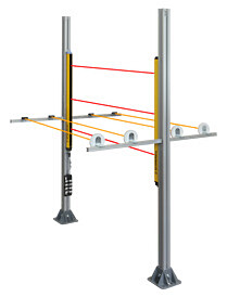
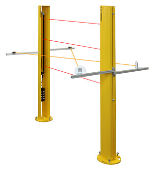
Mounting safety light grids / light curtains or deflection mirrors
Aluminium profile with stand
Optional: Also suitable for mounting muting cantilever
103055512
| MS-MST-SG |
- Muting mounting set T-version consisting of 4 aluminium profiles (20x20x400mm) attached to the SG with 2 SG U-brackets

103005653 MS-MSL-01
- Muting carrier set L-Version consists 2pcs of aluminium-profiles (20x20x400mm) fixed at MST profile
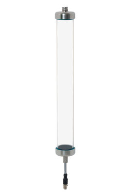
103055815 SH-445-ER-02
- Protective enclosure for SLC/SLG445
- Extremely robust protective tube made of polycarbonate
- Impact resistant - Break resistant - Scratch resistant - Hygienic
- End plugs, membrane and cable entry made of stainless steel
- Protection class IP69
- ECOLAB certified
101214875 KA-0845
- Connection cable for SLC/SLG445 transmitter to MCU-02, M12/4-pin, M12/4-pin
- Pre-wired cable
- 4-pole
- for SLC/SLG
103005657 KA-0846
- Connection cable for muting sensor, M8 coupling, M12 plug, 4-pin
- Pre-wired cable
- 4-pole
- for SLC/SLG
103005658 KA-0847
- Connection cable for muting sensor, M8 coupling, M12 plug, 4-pin
- Pre-wired cable
- 4-pole
- for SLC/SLG
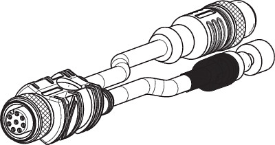
103005575 KA-0976
- Cable for parameterisation SLC/SLG445, 2 x M12/12-pin, push-button
- Pre-wired cable
- for SLC/SLG
| EU-Konformitätserklärung |  |
| Original | Safety Control GmbH Am Industriepark 2a 84453 Mühldorf / Inn Germany |
| Erklärung: | Hiermit erklären wir, dass die nachfolgend aufgeführten Bauteile aufgrund der Konzipierung und Bauart den Anforderungen der unten angeführten Europäischen Richtlinien entsprechen. |
| Bezeichnung des Bauteils: | SLC445 SLG445 |
| Typ: | siehe Typenschlüssel |
| Beschreibung des Bauteils: | Sicherheits-Lichtvorhang / -Lichtgitter |
| Einschlägige Richtlinien: | Maschinenrichtlinie | 2006/42/EG |
| EMV-Richtlinie | 2014/30/EU | |
| RoHS-Richtlinie | 2011/65/EU |
| Angewandte Normen: | EN 61496-1:2013 EN 61496-2:2013 EN ISO 13849-1:2015 EN 62061:2005 + AC:2010 + A1:2013 + A2:2015 |
| Benannte Stelle der Baumusterprüfung: | TÜV NORD CERT GmbH Langemarckstr. 20, 45141 Essen Kenn-Nr.: 0044 |
| EG-Baumusterprüfbescheinigung: | 44 205 13144604 |
| Bevollmächtigter für die Zusammenstellung der technischen Unterlagen: | Oliver Wacker Möddinghofe 30 42279 Wuppertal |
| Ort und Datum der Ausstellung: | Mühldorf, 10. Juni 2020 |
 |  |
| Rechtsverbindliche Unterschrift Klaus Schuster Geschäftsführer | Rechtsverbindliche Unterschrift Christian Spranger Geschäftsführer |
Schmersal India Pvt. Ltd., Plot No - G-7/1, Ranjangaon MIDC, Tal. - Shirur, Dist.- Pune 412 220
Die genannten Daten und Angaben wurden sorgfältig geprüft. Abbildungen können vom Original abweichen. Weitere technische Daten finden Sie in der Betriebsanleitung. Technische Änderungen und Irrtümer vorbehalten.
Generiert am: 16.06.2025, 20:51