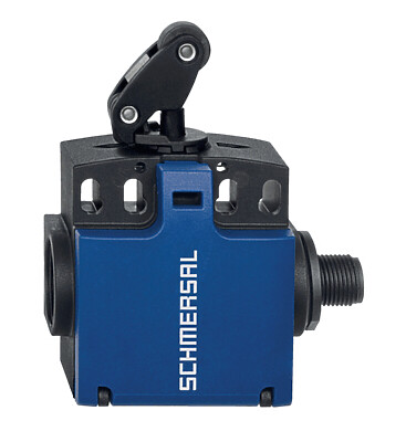
AZM 161 Z ST2-AS R

AZM 161 Z ST2-AS R
| Product type description: AZM 161 (1) (2)-AS (3)(4)(5)(6) |
| (1) | |
| Z | Guard locking monitored > |
| B | Actuator monitored |
| BZ | Combined monitoring of actuator and solenoid interlock |
| (2) | |
| ST1 | Bottom-side connector |
| ST2 | Connector at the right-hand side |
| (3) | |
| without | Latching force 5 N |
| R | Latching force 30 N |
| (4) | |
| without | Power to unlock |
| A | Power to lock |
| (5) | |
| without | Magnet supply from AS-Interface |
| P | Magnet supply 24 VDC (AUX) |
| (6) | |
| without | Manual release |
| N | Emergency release |
| T | Emergency exit |
- Solenoid supply AUS AS interface
- Guard locking monitored
- Manual release
- Solenoid interlock
- Thermoplastic enclosure
- High holding force 2000
- 130 mm x 90 mm x 30 mm
- Interlock with protection against incorrect locking.
- Double-insulated
- Long life
- Integrated AS-Interface
Ordering data
| Product type description |
AZM 161 Z ST2-AS R |
| Article number (order number) |
101209111 |
| EAN (European Article Number) |
4030661399744 |
| eCl@ss number, version 12.0 |
27-27-26-03 |
| eCl@ss number, version 11.0 |
27-27-26-03 |
| eCl@ss number, version 9.0 |
27-27-26-03 |
| ETIM number, version 7.0 |
EC002593 |
| ETIM number, version 6.0 |
EC002593 |
Approvals - Standards
| Certificates |
cULus ASi-SaW |
General data
| Standards |
EN IEC 62026-2 EN ISO 13849-1 EN IEC 60947-5-1 EN IEC 61508 |
| Coding level according to EN ISO 14119 |
Low |
| Working principle |
electromechanical |
| Housing material |
Plastic, glass-fibre reinforced thermoplastic, self-extinguishing |
| Reaction time, maximum |
100 ms |
| Gross weight |
480 g |
General data - Features
| Power to unlock |
Yes |
| Solenoid interlock monitored |
Yes |
| Manual release |
Yes |
| Integral system diagnostics, status |
Yes |
| Number of actuating directions |
3 |
| Safety classification |
| Vorschriften |
EN ISO 13849-1 EN IEC 61508 |
| Performance Level, up to |
c |
| Category |
1 |
| PFH value |
1.14 x 10⁻⁶ /h |
| Note (PFH-value) |
up to max. 100,000 switching cycles/year |
| Safety Integrity Level (SIL), suitable for applications in |
1 |
| Mission time |
20 Year(s) |
| Safety classification - Fault exclusion |
| Please note: |
Can be used when fault exclusion for dangerous damage to the 1-channel mechanism is permissible and sufficient protection against manipulation is guaranteed. |
| Performance Level, up to |
d |
| Category |
3 |
| PFH value |
1.01 x 10⁻⁷ /h |
| Note (PFH-value) |
up to max. 100,000 switching cycles/year |
| Safety Integrity Level (SIL), suitable for applications in |
2 |
| Mission time |
20 Year(s) |
Safety classification - Guard locking function
| Performance Level, up to |
e |
| Note (Performance Level) |
Information for the safety classification of the guard locking function is documented in the "Operating instructions" or in the "Operation and mounting" instructions. |
Mechanical data
| Mechanical life, minimum |
1,000,000 Operations |
| Actuating play in direction of actuation |
5.5 mm |
| Holding force FZh in accordance with EN ISO 14119 |
2,000 N |
| Holding force Fmax, maximum |
2,600 N |
| Latching force |
30 N |
| Actuating speed, maximum |
2 m/s |
| Mounting |
Screws |
| Type of the fixing screws |
3x M6 |
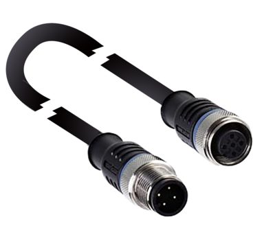
Mechanical data - Connection technique
| Connector position |
Right |
| Termination |
Connector plug M12, 4-pole, (A-coding) |
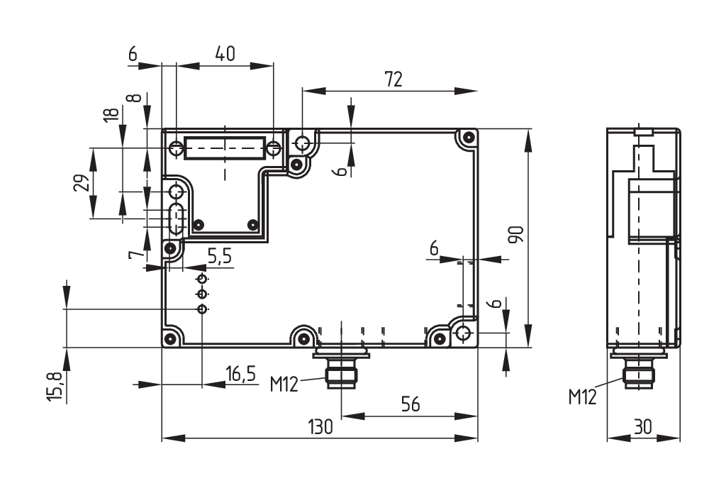
Mechanical data - Dimensions
| Length of sensor |
30 mm |
| Width of sensor |
130 mm |
| Height of sensor |
90 mm |
Ambient conditions
| Degree of protection |
IP67 |
| Ambient temperature |
-25 ... +60 °C |
| Storage and transport temperature |
-25 ... +85 °C |
| Relative humidity, minimum |
30 % |
| Relative humidity, maximum |
95 % |
| Note (Relative humidity) |
non-condensing non-icing |
| Resistance to vibrations |
10 … 150 Hz, amplitude 0.35 mm |
| Restistance to shock |
30 g / 11 ms |
| Protection class |
II |
| Permissible installation altitude above sea level, maximum |
2,000 m |
Ambient conditions - Insulation values
| Rated insulation voltage Ui |
32 VDC |
| Rated impulse withstand voltage Uimp |
0.8 kV |
| Overvoltage category |
III |
| Degree of pollution |
3 |
Electrical data
| Maximale Schalthäufigkeit |
1,000 /h |
Electrical data - AS Interface
| Rated operating voltage |
26.5 ... 31.6 VDC (Protection against polarity reversal) |
| AS-i Current consumption, maximum |
250 mA |
Electrical data - AS-Interface specification
| AS-i Specification |
Safety-Slave |
| AS-i Version |
V 2.1 |
| AS-i Profile |
S-7.B.F.E |
| AS-i, IO-Code |
0x7 |
| AS-i, ID-Code |
0xB |
| AS-i, ID-Code1 |
0xF |
| AS-i, ID-Code2 |
0xE |
| AS-i Input, Channel 1 |
Data bits DI 0 / DI 1 = dynamic code transmission |
| AS-i Input, Channel 2 |
Data bits DI 2 / DI 3 = dynamic code transmission |
| AS-i Outputs, DO 0 |
Solenoid control |
| AS-i Outputs, DO 1 |
No Function |
| AS-i Outputs, DO 2 |
No Function |
| AS-i Outputs, DO 3 |
No Function |
| AS-i Parameter bits, P0 |
Actuator detected |
| AS-i Parameter bits, P1 |
Solenoid interlock locked |
| AS-i Parameter bits, P2 |
Magnet voltage in tolerance range |
| AS-i Parameter bits, P3 |
Error message - locking/unlocking of the solenoid interlock blocked |
| Note (AS-i Parameter bits) |
Set the parameter outputs to "1111" (0xF) FID: periphery error |
| AS-i Input module address |
0 |
| Note (AS-i Input module address) |
Preset to address 0, can be changed through AS-interface bus master or hand-held programming device |
Status indication
| Note (LED switching conditions display) |
(1) LED yellow: Channel 2 / AS-i SaW Bit 2.3 (2) LED green/red (AS-i duo LED): Supply voltage / communication error / slave address = 0 / periphery error detected (3) LED yellow: Channel 1 / AS-i SaW Bit 0.1 |
Other data
| Note (applications) |
sliding safety guard removable guard hinged safety guard |
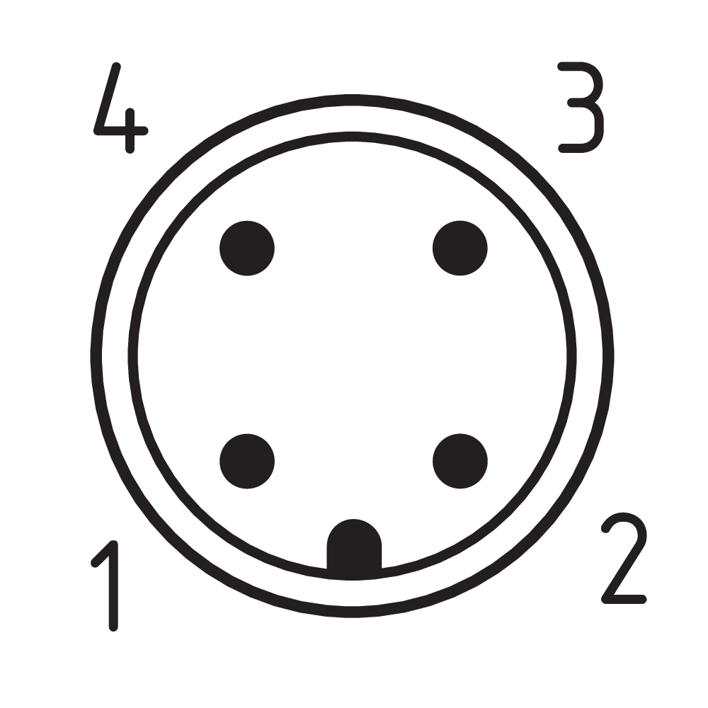
Pin assignment
| PIN 1 |
AS-i + |
| PIN 2 |
n.c. |
| PIN 3 |
AS-Interface - |
| PIN 4 |
n.c. |
Scope of delivery
| Scope of delivery |
Actuator must be ordered separately. |
Note
| Note (General) |
Interlocks with the power to lock principle may only be used in special cases after a thorough evaluation of the accident risk, since the guarding device can immediately be opened on failure of the electrical power supply or when the main switch is opened. |
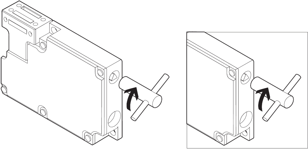
| Note (Manual release) |
For maintenance, installation, etc. For manual release using M5 triangular key, available as accessory |
Language filter
Datasheet
Operating instructions and Declaration of conformity
UL Certificate
AS interface safety at work certificate
SISTEMA-VDMA library
Download the latest version of Adobe Reader
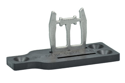
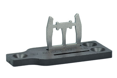
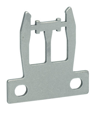
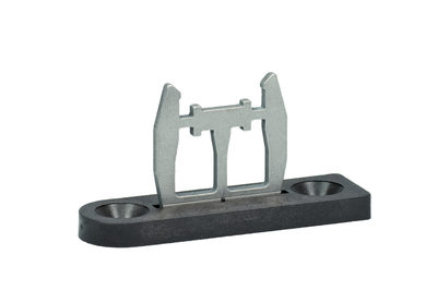
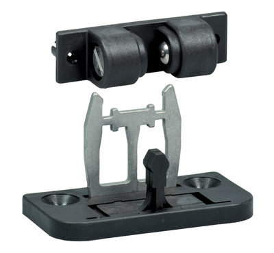
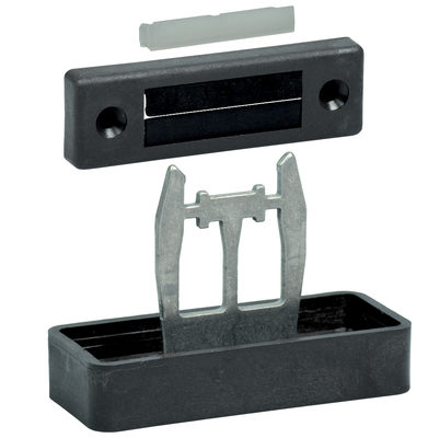
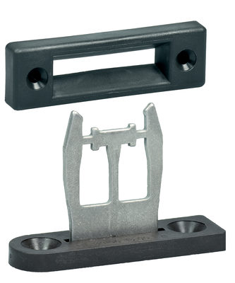
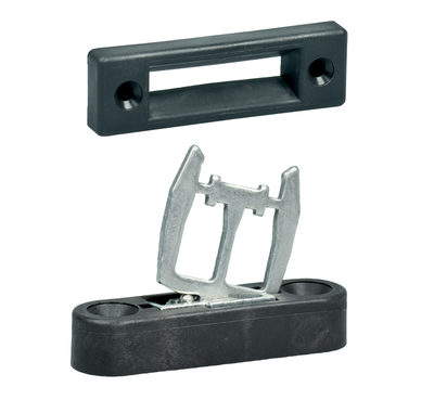
Product picture (catalogue individual photo)

ID: kazm1f54
| 435.8 kB | .jpg | 352.778 x 224.719 mm - 1000 x 637 px - 72 dpi
| 44.9 kB | .png | 74.083 x 47.272 mm - 210 x 134 px - 72 dpi
| 356.1 kB | .jpg | 352.778 x 224.719 mm - 1000 x 637 px - 72 dpi
| 39.9 kB | .png | 74.083 x 47.272 mm - 210 x 134 px - 72 dpi
| 39.9 kB | .png | 74.083 x 47.272 mm - 210 x 134 px - 72 dpi
Dimensional drawing basic component
Contact arrangement
Operating principle
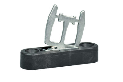
101145117 ACTUATOR AZM 161-B1
- Straight actuator
- Particularly suitable for sliding doors
101144416 ACTUATOR AZM 161-B1E
- Straight actuator
- Particularly suitable for sliding doors
101171859 ACTUATOR AZM 161-B1ES
- Straight actuator
- Particularly suitable for sliding doors
101175431 ACTUATOR AZM 161-B1F
- Straight actuator
- Particularly suitable for sliding doors
101171125 BETAETIGER AZM 161-B1S
- Straight actuator
- Particularly suitable for sliding doors
101173089 AZM 161-B1-2053 RETROFIT KIT
- Straight actuator
- Particularly suitable for sliding doors
- adjustable ball latch

101164100 AZM 161-B1-1747 RETROFIT KIT
- Straight actuator with magnetic latch
- Particularly suitable for sliding doors
101178199 AZM 161-B1-2024
- Straight actuator with slot lip-seal
- Particularly suitable for sliding doors
101176642 AZM 161-B1-2177 RETROFIT KIT
- Straight actuator with centering guide
- Particularly suitable for sliding doors
101174113 AZM 161-B6-2177 WITH CENTERING GUIDE
- For very smal actuating radii
101170375 BETAETIGER AZM 161-B6S
- For very smal actuating radii
101144420 ACTUATOR AZM 161-B6
- Flexible actuator
- Particularly suitable for hinged guards
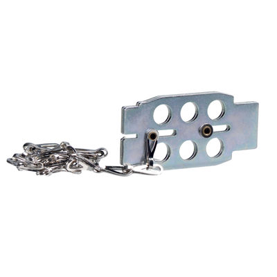
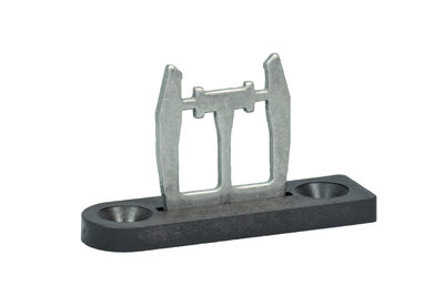
101110500 LOCKOUT TAG SZ 16/335
- To prevent inadvertent closing, e.g. during maintenance
- For complex plant
- Prevents actuation of the switch
- Up to 6 padlocks can be fitted
- The lockout tag can be mounted on a chain near to the safety switch
| EU Declaration of Conformity |  |
| Original | K.A. Schmersal GmbH & Co. KG Möddinghofe 30 42279 Wuppertal Germany Internet: www.schmersal.com |
| Declaration: | We hereby certify that the hereafter described components both in their basic design and construction conform to the applicable European Directives. |
| Name of the component: | AZM 161 AS |
| Type: | See ordering code |
| Description of the component: | Interlocking device with electromagnetic interlock for safety functions with integrated AS-i Safety at Work |
| Relevant Directives: | Machinery Directive | 2006/42/EC |
| EMC-Directive | 2014/30/EU | |
| RoHS-Directive | 2011/65/EU |
| Applied standards: | EN 60947-5-1:2017 EN ISO 14119:2013 EN ISO 13849-1:2015 EN 61508 parts 1-7:2010 |
| Person authorised for the compilation of the technical documentation: | Oliver Wacker Möddinghofe 30 42279 Wuppertal |
| Place and date of issue: | Wuppertal, August 3, 2020 |
 |
| Authorised signature Philip Schmersal Managing Director |
Schmersal Ltd., Sparrowhawk Close, WR14 1GL Malvern
The details and data referred to have been carefully checked. Images may diverge from original. Further technical data can be found in the manual. Technical amendments and errors possible.
Generated on: 10/07/2025, 14:46
Recently viewed

AZM 200ST2-T-1P2PW
PS226-Z02-STR-K200
LF 50-11 P
T3C 235-01Z