SRB201LC
SRB201LC
- Suitable for the signal processing of outputs with contact sensors
- 2 safety contacts, STOP 0
- 1 Signalling output
Ordering data
| Product type description |
SRB201LC |
| Article number (order number) |
101212555 |
| EAN (European Article Number) |
4030661448916 |
| eCl@ss number, version 12.0 |
27-37-18-19 |
| eCl@ss number, version 11.0 |
27-37-18-19 |
| eCl@ss number, version 9.0 |
27-37-18-19 |
| ETIM number, version 7.0 |
EC001449 |
| ETIM number, version 6.0 |
EC001449 |
| Notice |
Discontinued product |
Approvals - Standards
| Certificates |
TÜV cULus |
General data
| Standards |
EN IEC 62061 EN ISO 13849-1 EN IEC 60947-5-1 EN IEC 60947-5-3 EN IEC 60947-5-5 EN IEC 61508 EN IEC 60204-1 EN IEC 60947-1 |
| Climatic stress |
EN 60068-2-78 |
| Housing material |
Plástico reforzado con fibra de vidrio, ventilador |
| Gross weight |
200 g |
General data - Features
| Wire breakage detection |
Sí |
| Feedback circuit |
Sí |
| Automatic reset function |
Sí |
| Earth connection detection |
Sí |
| Integral system diagnostics, status |
Sí |
| Number of LEDs |
3 |
| Number of normally closed (NC) |
2 |
| Number of undelayed semi-conductor outputs with signaling function |
1 |
| Number of safety contacts |
2 |
| Number of signalling outputs |
1 |
| Safety classification |
| Vorschriften |
EN IEC 60947-5-1 EN IEC 61508 |
| Stop-Category |
0 1 |
| Safety classification - Relay outputs |
| Performance Level, stop 0, up to |
e |
| Category, Stop 0 |
4 |
| Diagnostic Coverage (DC) Level, Stop 0 |
≥ 99 % |
| PFH value, Stop 0 |
2,00 x 10⁻⁸ /h |
| Safety Integrity Level (SIL), Stop 0, suitable for applications in |
3 |
| Mission time |
20 Year(s) |
| Common Cause Failure (CCF), minimum |
65 |
Mechanical data
| Mechanical life, minimum |
10.000.000 Operations |
| Mounting |
Sujeción rápida para carriles normalizados según DIN EN 60715 |
Mechanical data - Connection technique
| Terminal designations |
IEC/EN 60947-1 |
| Termination |
rígido o flexible Terminales con tornillo M20 x 1.5 |
| Cable section, minimum |
0,25 mm² |
| Cable section, maximum |
2,5 mm² |
| Tightening torque of Clips |
0,6 Nm |
Mechanical data - Dimensions
| Width |
22,5 mm |
| Height |
100 mm |
| Depth |
121 mm |
Ambient conditions
| Degree of protection of the enclosure |
IP40 |
| Degree of protection of the mounting space |
IP54 |
| Degree of protection of clips or terminals |
IP20 |
| Ambient temperature |
-25 ... +60 °C |
| Storage and transport temperature |
-40 ... +85 °C |
| Resistance to vibrations |
10...55 Hz, amplitud 0,35 mm, ± 15 % |
| Restistance to shock |
10 g / 11 ms |
Ambient conditions - Insulation values
| Rated impulse withstand voltage Uimp |
4 kV |
| Overvoltage category |
III |
| Degree of pollution |
2 |
Electrical data
| Frequency range |
50 Hz 60 Hz |
| Operating voltage |
24 VAC -15 % / +10 % |
| Ripple voltage |
10 % |
| Rated operating voltage |
24 VAC |
| Rated operating voltage |
24 VDC |
| Rated AC voltage for controls, 50 Hz, minimum |
20,4 VAC |
| Rated control voltage at AC 50 Hz, maximum |
26,4 VAC |
| Rated AC voltage for controls, 60 Hz, minimum |
20,4 VAC |
| Rated control voltage at AC 60 Hz, maximum |
26,4 VAC |
| Rated AC voltage for controls at DC minimum |
20,4 VDC |
| Rated control voltage at DC, maximum |
28,8 VDC |
| Electrical power consumption |
2 W |
| Electrical power consumption |
5,2 VA |
| Contact resistance, maximum |
0,1 Ω |
| Note (Contact resistance) |
en estado nuevo |
| Drop-out delay in case of power failure, typically |
80 ms |
| Drop-out delay in case of emergency, typically |
20 ms |
| Pull-in delay at automatic start, maximum, typically |
100 ms |
| Pull-in delay at RESET, typically |
20 ms |
| Material of the contacts, electrical |
AgSn0. autolimpiante, guiado monitorizado |
Electrical data - Safe relay outputs
| Voltage, Utilisation category AC-15 |
230 VAC |
| Current, Utilisation category AC-15 |
6 A |
| Voltage, Utilisation category DC-13 |
24 VDC |
| Current, Utilisation category DC-13 |
6 A |
| Switching capacity, minimum |
10 VDC |
| Switching capacity, minimum |
10 mA |
| Switching capacity, maximum |
250 VAC |
| Switching capacity, maximum |
8 A |
Electrical data - Digital inputs
| Conduction resistance, maximum |
40 Ω |
Electrical data - Relay outputs (auxiliary contacts)
| Switching capacity, maximum |
24 VDC |
| Switching capacity, maximum |
2 A |
Electrical data - Electromagnetic compatibility (EMC)
| EMC rating |
Directiva sobre compatibilidad electromagnética CEM |
Status indication
| Indicated operating states |
Posición de los relés K2 Posición de ls relés K1 Tensión de servicio interna Ui |
Other data
| Note (applications) |
Resguardo de seguridad Pulsador de Paro de Emergencia Interruptor de Paro de Emergencia por tracción de cable Cortina óptica de seguridad |
Note
| Note (General) |
Obciążenia indukcyjne (np. styczniki, przekaźniki itp.) należy wytłumić przy pomocy odpowiedniego obwodu. |
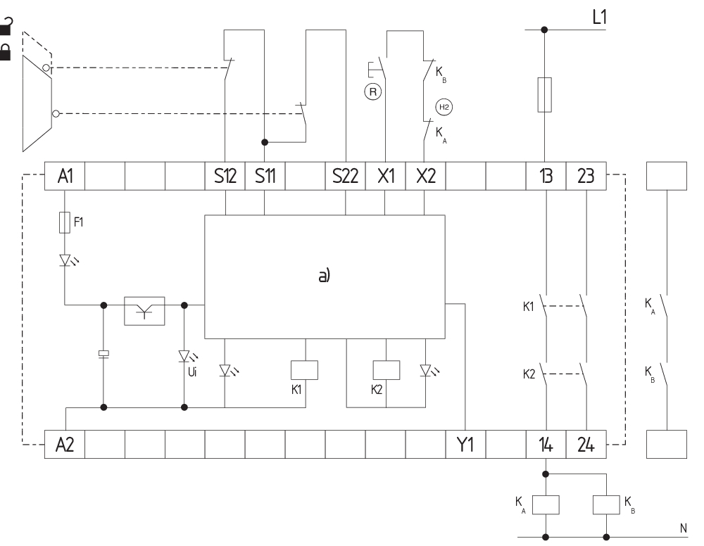
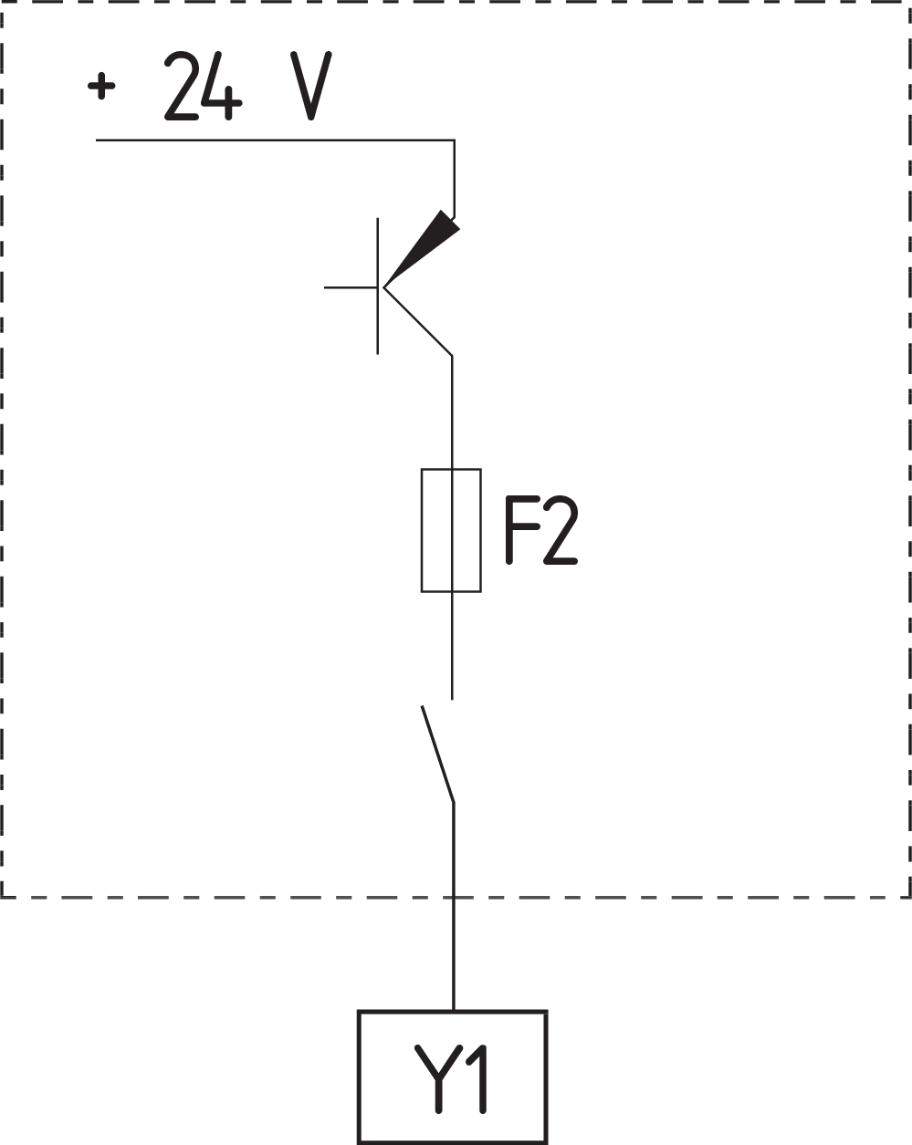
Wiring example
| Note (Wiring diagram) |
El esquema de cableado se muestra con todos los resguardos de seguridad cerrados y sin alimentación. Campos de potencia: diseñado para control de 2 canales, para reforzar los contactos, o bien para ampliar su número, utilizar contactores o relés con los contactos de guía forzada. Arranque automático: La programación del arranque automático se realiza a través del enlace del circuito de realimentación a los terminales X1/X2. Caso de no utilizar el circuito de realimentación, debe sustituirse por un puente. El control detecta cruces entre hilos, roturas de cable y cortocircuitos a tierra del circuito de monitorización. Planos de entrada: Control de 2 canales, referido, por ejemplo, a la vigilancia de uno resguardo de seguridad con dos interruptores de posición, uno de ellos con apertura forzada, pulsador externo de rearme (R); vigilancia de cierre transversal y circuito de realimentación (H2). En caso de control de 1 canal conecte el contacto NC a la alimentación y puente entre S11/S12 y S21/S22. |
Filtro de idiomas
Ficha técnica
Manual de instrucciones y declaración de conformidad
Certificado UL
SISTEMA-VDMA Biblioteca/Library
Descargar la versión actual de Adobe Reader
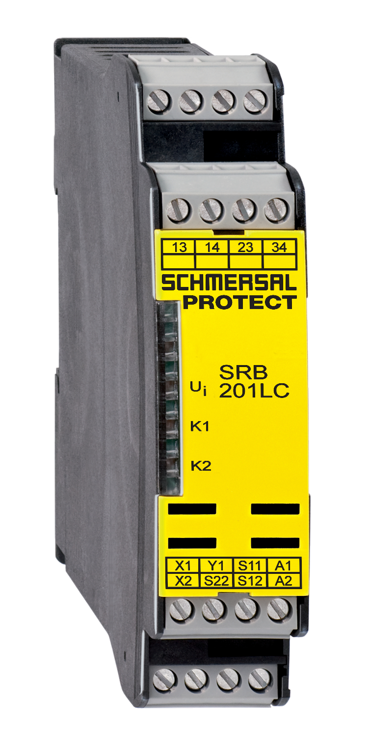
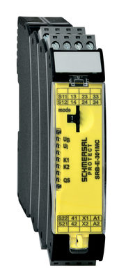
Foto de producto (foto individual de catálogo)
Ejemplo de cableado
Ejemplo de cableado
Ejemplo de cableado
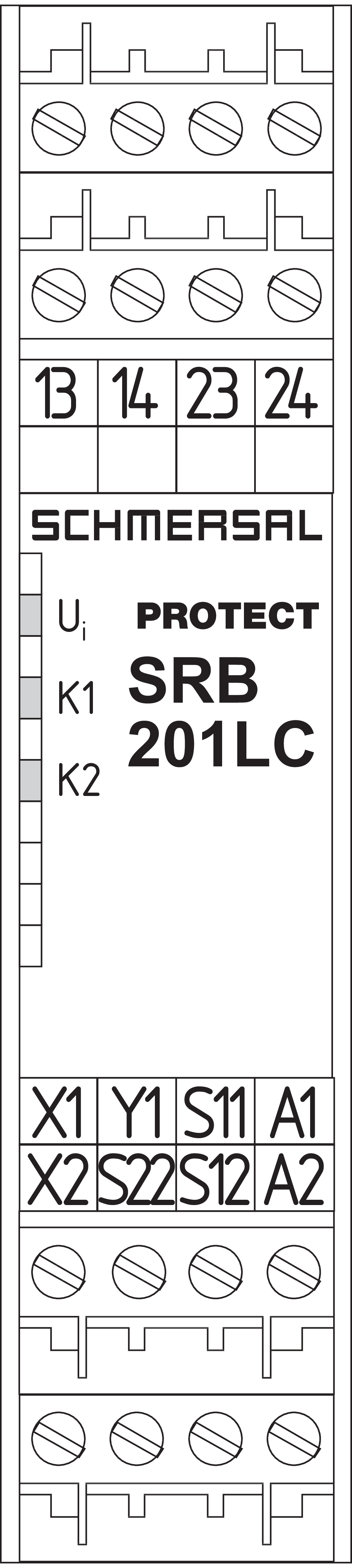
Símbolo (estandar técnico)


103009970 SRB-E-201LC
- Plug-in screw terminals with coding
- STOP 0 Function
- 1 oder 2-channel control
- Start button / Auto-start
- 2 Safety outputs 2 A
- 1 Signalling output
103014374 SRB-E-301MC
- 1 Signalling contact
- Plug-in screw terminals with coding
- Suitable for applications up to Cat. 4 / PL e und up to SIL 3
- 1 or 2 channel signal evaluation
- Start / feedback circuit monitoring
- Optionally with short-circuit recognition
- 3 safety contacts, stop category 0
| EU Declaration of Conformity |  |
| Original | K.A. Schmersal GmbH & Co. KG Möddinghofe 30 42279 Wuppertal Germany Internet: www.schmersal.com |
| Declaration: | We hereby certify that the hereafter described components both in their basic design and construction conform to the applicable European Directives. |
| Name of the component: | SRB201LC |
| Description of the component: | Relay-safety combination for emergency stop circuits, guard door monitoring, solenoid safety switches and AOPD’s |
| Relevant Directives: | Machinery Directive | 2006/42/EC |
| EMC-Directive | 2014/30/EU | |
| RoHS-Directive | 2011/65/EU |
| Applied standards: | EN 60947-5-3:2013 EN 50178:1997 EN ISO 13849-1:2015 IEC 61508 parts 1 to 7:2010 |
| Notified body for Type Examination: | TÜV Rheinland Industrie Service GmbH Am Grauen Stein, 51105 Köln ID n°: 0035 |
| EC-Type Examination Certificate: | 01/205/0734.02/20 |
| Person authorised for the compilation of the technical documentation: | Oliver Wacker Möddinghofe 30 42279 Wuppertal |
| Ort und Datum der Ausstellung: | Wuppertal, November 16, 2020 |
 |
| Authorised signature Philip Schmersal Managing Director |
Schmersal India Pvt. Ltd., Plot No - G-7/1, Ranjangaon MIDC, Tal. - Shirur, Dist.- Pune 412 220
Los datos e información anteriores se han verificado cuidadosamente. Las imágenes pueden diferir del original. Se pueden encontrar más datos técnicos en los manuales de instrucciones. Sujeto a cambios técnicos y errores.
Generado a 11/4/2025 23:46
Historial

ACTUATOR AZ 17/170-B1