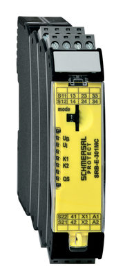
SRB201LC
SRB201LC
- Suitable for the signal processing of outputs with contact sensors
- 2 safety contacts, STOP 0
- 1 Signalling output
Ordering data
| Product type description |
SRB201LC |
| Article number (order number) |
101212555 |
| EAN (European Article Number) |
4030661448916 |
| eCl@ss number, version 12.0 |
27-37-18-19 |
| eCl@ss number, version 11.0 |
27-37-18-19 |
| eCl@ss number, version 9.0 |
27-37-18-19 |
| ETIM number, version 7.0 |
EC001449 |
| ETIM number, version 6.0 |
EC001449 |
| Notice |
Discontinued product |
Approvals - Standards
| Certificates |
cULus |
General data
| Standards |
EN IEC 62061 EN ISO 13849-1 EN IEC 60947-5-1 EN IEC 60947-5-3 EN IEC 60947-5-5 EN IEC 61508 EN IEC 60204-1 EN IEC 60947-1 |
| Climatic stress |
EN 60068-2-78 |
| Housing material |
Glass-fibre reinforced thermoplastic, ventilated |
| Gross weight |
200 g |
General data - Features
| Wire breakage detection |
Yes |
| Feedback circuit |
Yes |
| Automatic reset function |
Yes |
| Earth connection detection |
Yes |
| Integral system diagnostics, status |
Yes |
| Number of LEDs |
3 |
| Number of normally closed (NC) |
2 |
| Number of undelayed semi-conductor outputs with signaling function |
1 |
| Number of safety contacts |
2 |
| Number of signalling outputs |
1 |
| Safety classification |
| Standards |
EN IEC 60947-5-1 EN IEC 61508 |
| Stop-Category |
0 1 |
| Safety classification - Relay outputs |
| Performance Level, stop 0, up to |
e |
| Category, Stop 0 |
4 |
| Diagnostic Coverage (DC) Level, Stop 0 |
≥ 99 % |
| PFH value, Stop 0 |
2.00 x 10⁻⁸ /h |
| Safety Integrity Level (SIL), Stop 0, suitable for applications in |
3 |
| Mission time |
20 Year(s) |
| Common Cause Failure (CCF), minimum |
65 |
Mechanical data
| Mechanical lifetime, minimum |
10,000,000 Operations |
| Mounting |
Snaps onto standard DIN rail to EN 60715 |
Mechanical data - Connection technique
| Terminal designations |
IEC/EN 60947-1 |
| Cable section, minimum |
0.25 mm² |
| Cable section, maximum |
2.5 mm² |
| Tightening torque of Clips |
0.6 Nm |
| Allowed type of cable |
solid single-wire flexible |
| Terminal (mechanical) |
Schraubklemmen |
Mechanical data - Dimensions
| Width |
22.5 mm |
| Height |
100 mm |
| Depth |
121 mm |
Ambient conditions
| Degree of protection of the enclosure |
IP40 |
| Degree of protection of the installation space |
IP54 |
| Degree of protection of clips or terminals |
IP20 |
| Ambient temperature |
-25 ... +60 °C |
| Storage and transport temperature |
-40 ... +85 °C |
| Resistance to vibrations |
10...55 Hz, Amplitude 0.35 mm, ± 15 % |
| Restistance to shock |
10 g / 11 ms |
Ambient conditions - Insulation values
| Rated impulse withstand voltage Uimp |
4 kV |
| Overvoltage category |
III |
| Degree of pollution |
2 |
Electrical data
| Frequency range |
50 Hz 60 Hz |
| Operating voltage |
24 VAC -15 % / +10 % |
| Ripple voltage |
10 % |
| Rated operating voltage |
24 VAC |
| Rated operating voltage |
24 VDC |
| Rated AC voltage for controls, 50 Hz, minimum |
20.4 VAC |
| Rated control voltage at AC 50 Hz, maximum |
26.4 VAC |
| Rated AC voltage for controls, 60 Hz, minimum |
20.4 VAC |
| Rated control voltage at AC 60 Hz, maximum |
26.4 VAC |
| Rated AC voltage for controls at DC minimum |
20.4 VDC |
| Rated control voltage at DC, maximum |
28.8 VDC |
| Electrical power consumption |
2 W |
| Electrical power consumption |
5.2 VA |
| Contact resistance, maximum |
0.1 Ω |
| Note (Contact resistance) |
in new state |
| Drop-out delay in case of power failure, typically |
80 ms |
| Drop-out delay in case of emergency, typically |
20 ms |
| Pull-in delay at automatic start, maximum, typically |
100 ms |
| Pull-in delay at RESET, typically |
20 ms |
| Material of the contacts, electrical |
AgSn0. self-cleaning, positive drive |
Electrical data - Safe relay outputs
| Voltage, Utilisation category AC-15 |
230 VAC |
| Current, Utilisation category AC-15 |
6 A |
| Voltage, Utilisation category DC-13 |
24 VDC |
| Current, Utilisation category DC-13 |
6 A |
| Switching capacity, minimum |
10 VDC |
| Switching capacity, minimum |
10 mA |
| Switching capacity, maximum |
250 VAC |
| Switching capacity, maximum |
8 A |
Electrical data - Digital inputs
| Conduction resistance, maximum |
40 Ω |
Electrical data - Relay outputs (auxiliary contacts)
| Switching capacity, maximum |
24 VDC |
| Switching capacity, maximum |
2 A |
Electrical data - Electromagnetic compatibility (EMC)
| EMC rating |
EMC-Directive |
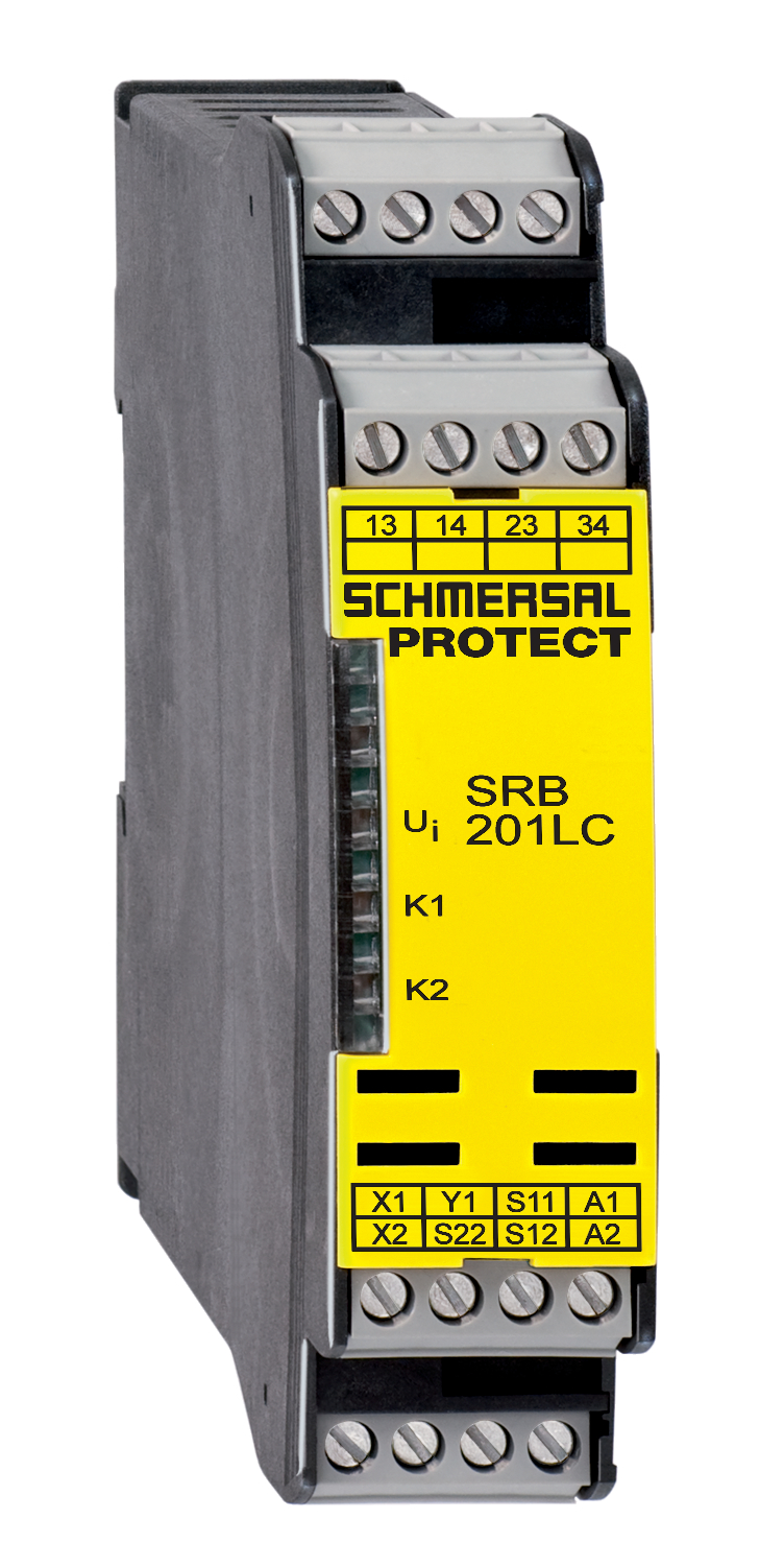
Status indication
| Indicated operating states |
Position relay K2 Position relay K1 Internal operating voltage Ui |
Other data
| Note (applications) |
Guard system Emergency-Stop button Pull-wire emergency stop switches Safety light curtain |
Note
| Note (General) |
Inductive loads (e.g. contactors, relays, etc.) are to be suppressed by means of a suitable circuit. |
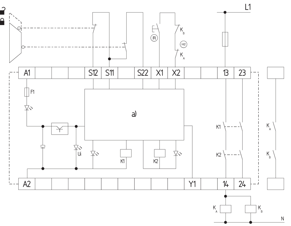
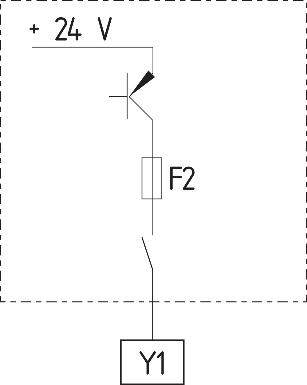
Wiring example
| Note (Wiring diagram) |
The wiring diagram is shown with guard doors closed and in de-energised condition. Relay outputs: Suitable for 2 channel control, for increase in capacity or number of contacts by means of contactors or relays with positive-guided contacts. Automatic start: The automatic start is programmed by connecting the feedback circuit to the terminals X1/X2. If the feedback circuit is not required, establish a bridge. The control recognises cross-short, cable break and earth leakages in the monitoring circuit. Input level: The example shows a 2-channel control of a guard door monitoring with two position switches, whereof one with positive break, external reset button (R); cross-wire monitoring and feedback circuit (H2) In case of a 1-channel control, connect the NC contact to the operating voltage and bridge S11/S12 and S21/S22. |
Language filter
Datasheet
Operating instructions and Declaration of conformity
UL Certificate
SISTEMA-VDMA library
Download the latest version of Adobe Reader
Product picture (catalogue individual photo)
Wiring example
Wiring example
Wiring example
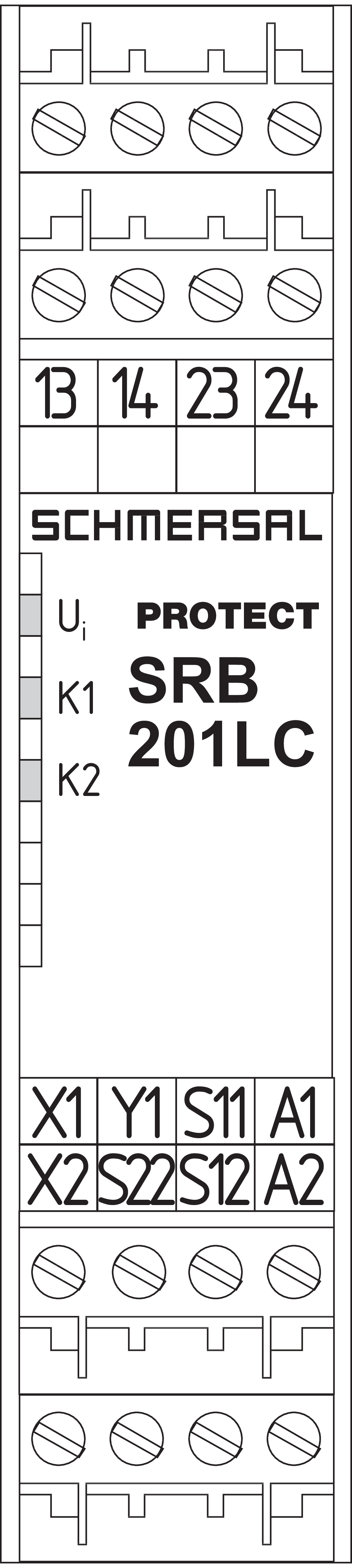
Symbol (technical standard)


103009970 SRB-E-201LC
- Plug-in screw terminals with coding
- STOP 0 Function
- 1 oder 2-channel control
- Start button / Auto-start
- 2 Safety outputs 2 A
- 1 Signalling output
103014374 SRB-E-301MC
- 1 Signalling contact
- Plug-in screw terminals with coding
- Suitable for applications up to Cat. 4 / PL e und up to SIL 3
- 1 or 2 channel signal evaluation
- Start / feedback circuit monitoring
- Optionally with short-circuit recognition
- 3 safety contacts, stop category 0
| EU Declaration of Conformity |  |
| Original | K.A. Schmersal GmbH & Co. KG Möddinghofe 30 42279 Wuppertal Germany Internet: www.schmersal.com |
| Declaration: | We hereby certify that the hereafter described components both in their basic design and construction conform to the applicable European Directives. |
| Name of the component: | SRB201LC |
| Description of the component: | Relay-safety combination for emergency stop circuits, guard door monitoring, solenoid safety switches and AOPD’s |
| Relevant Directives: | Machinery Directive | 2006/42/EC |
| EMC-Directive | 2014/30/EU | |
| RoHS-Directive | 2011/65/EU |
| Applied standards: | EN 60947-5-3:2013 EN 50178:1997 EN ISO 13849-1:2015 IEC 61508 parts 1 to 7:2010 |
| Notified body for Type Examination: | TÜV Rheinland Industrie Service GmbH Am Grauen Stein, 51105 Köln ID n°: 0035 |
| EC-Type Examination Certificate: | 01/205/0734.02/20 |
| Person authorised for the compilation of the technical documentation: | Oliver Wacker Möddinghofe 30 42279 Wuppertal |
| Ort und Datum der Ausstellung: | Wuppertal, November 16, 2020 |
 |
| Authorised signature Philip Schmersal Managing Director |
K.A. Schmersal GmbH & Co. KG, Möddinghofe 30, 42279 Wuppertal
The details and data referred to have been carefully checked. Images may diverge from original. Further technical data can be found in the manual. Technical amendments and errors possible.
Generated on: 25/09/2025, 22:00
Recently viewed
BNS 260-02/01Z-R 10,0M
T5C 236-02Z-ST
SLC440COM-ER-1530-30

BDF200-NH-11-WS20-LTGN-LMBU
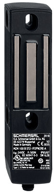
MZM 100 B ST2-SD2PRE-A
A-K4P-M8-S-G-10M-GY-1-X-X-4
KG443-A