CSP 11-34-D-M-ST
CSP 11-34-D-M-ST
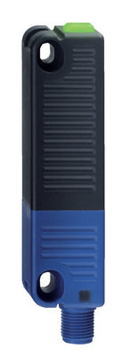
- 1 x connector plug M12, 8-pole
- Actuation from side
- without On-site acknowledgment
- NOTICE: Not available! (Replacement: RSS 36 I)
- Thermoplastic enclosure
- Electronic contact-free, coded system
- Tampering protection by paired coding of sensor and actuator
- Misaligned actuation possible
- High repeat accuracy of the switching points
- Max. length of the sensor chain 200 m
- 2 short-circuit proof PNP safety outputs
- Integral cross-short, wire-breakage and external voltage monitoring of the safety cables up to the control cabinet
Ordering data
| Note (Delivery capacity) |
Plus disponible! |
| Product type description |
CSP 11-34-D-M-ST |
| Article number (order number) |
101208004 |
| EAN (European Article Number) |
4030661382012 |
| eCl@ss number, version 12.0 |
27-27-26-06 |
| eCl@ss number, version 11.0 |
27-27-24-04 |
| eCl@ss number, version 9.0 |
27-27-24-04 |
| ETIM number, version 7.0 |
EC001487 |
| ETIM number, version 6.0 |
EC001487 |
Approvals - Standards
| Certificates |
cULus |
General data
| Standards |
EN ISO 13849-1 EN IEC 60947-5-3 EN IEC 61508 |
| Working principle |
inductif |
| Housing construction form |
Bloc |
| Installation conditions (mechanical) |
non affleuré |
| Sensor topology |
Connexion en série |
| Housing material |
Plastique, thermoplastique renforcé de fibres de verre |
| Active area |
Plastique, thermoplastique renforcé de fibres de verre |
| Reaction time, maximum |
30 ms |
| Duration of risk, maximum |
60 ms |
| Gross weight |
111 g |
General data - Features
| Diagnostic output |
Oui |
| Short circuit detection |
Oui |
| Cross-circuit detection |
Oui |
| Safety functions |
Oui |
| Cascadable |
Oui |
| Integral system diagnostics, status |
Oui |
| Number of LEDs |
3 |
| Number of semi-conductor outputs with signaling function |
1 |
| Number of fail-safe digital outputs |
2 |
| Number of series-wiring of sensors |
31 |
| Safety classification |
| Vorschriften |
EN IEC 60947-5-3 EN IEC 61508 |
| Performance Level, up to |
e |
| Category |
4 |
| PFH value |
3,60 x 10⁻⁹ /h |
| Safety Integrity Level (SIL), suitable for applications in |
3 |
| Mission time |
20 Year(s) |
Mechanical data
| Actuating panels |
latéral |
| Active area |
latéral |
Mechanical data - Switching distances
| Switch distance, typical |
11 mm |
| Assured switching distance "ON" Sao |
8 mm |
| Assured switching distance "OFF" Sar |
15 mm |
| Note (switching distance) |
All switching distances in accordance EN IEC 60947-5-3 |
| Hysteresis (Switching distance), maximum |
1,5 mm |
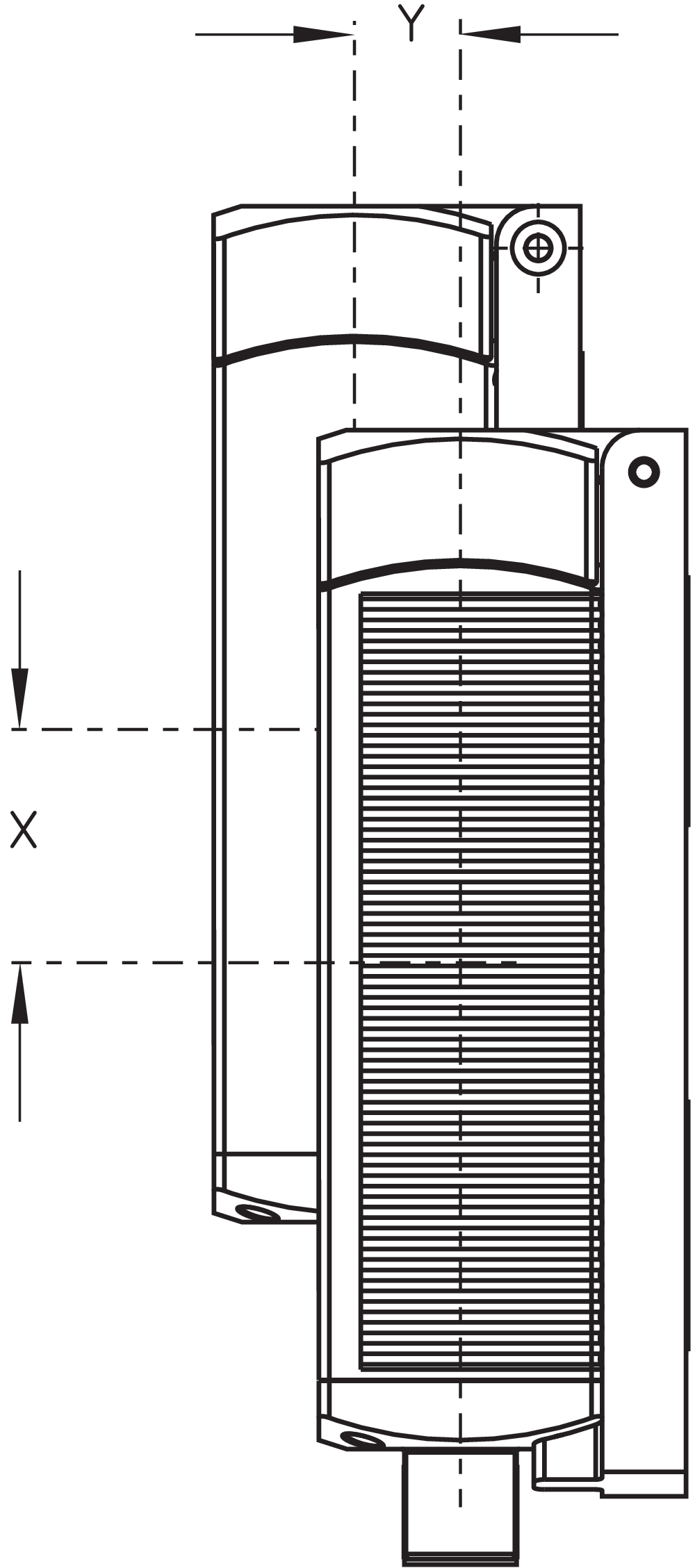
| Repeat accuracy R |
0,5 mm |
| Note (Repeat accuracy R) |
Décalage latéral: le côté long permet un décalage en hauteur max. (x) entre le capteur et l'actionneur de 30 mm (p.ex. suite aux erreurs de montage ou au désalignement du protecteur). Le décalage transversal (y) s'élève à max. ± 8 mm. |
Mechanical data - Connection technique
| Note (length of the sensor chain) |
Cable length and cross-section change the voltage drop dependiing on the output current |
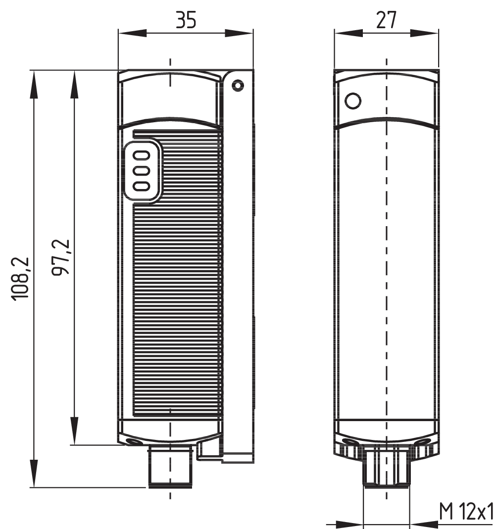
| Termination |
Connecteur intégré M12, 8 pôles |
Mechanical data - Dimensions
| Length of sensor |
27 mm |
| Width of sensor |
35 mm |
| Height of sensor |
108,2 mm |
Ambient conditions
| Degree of protection |
IP65 IP67 |
| Ambient temperature |
-25 ... +70 °C |
| Storage and transport temperature |
-25 ... +85 °C |
| Resistance to vibrations |
10…55 Hz, amplitude 1 mm |
| Restistance to shock |
30 g / 11 ms |
| Protection class |
II |
Ambient conditions - Insulation values
| Rated insulation voltage Ui |
32 VAC/DC |
| Rated impulse withstand voltage Uimp |
0,8 kV |
| Overvoltage category |
III |
| Degree of pollution |
3 |
Electrical data
| Operating voltage |
24 VDC -15 % / +10 % |
| No-load supply current I0, typical |
100 mA |
| Rated operating voltage |
24 VDC |
| Operating current |
600 mA |
| Required rated short-circuit current |
100 A |
| Utilisation category DC-12 |
24 VDC |
| Utilisation category DC-12 |
0,05 A |
| Utilisation category DC-13 |
24 VDC |
| Utilisation category DC-13 |
0,05 A |
| Note (Electrical data, Fuse rating) |
(Pour la protection des câbles) |
| Switching frequency, approx. |
3 Hz |
| Utilisation category DC-12 |
24 VDC / 0,05 A |
| Electrical fuse rating, maximum |
2 A |
Electrical data - Safety digital outputs
| Rated operating current (safety outputs) |
250 mA |
| Output current, (fail-safe output), maximum |
0,25 A |
| Design of control elements |
commutation P |
| Voltage drop Ud, maximum |
0,5 V |
| Leakage current Ir, maximum |
0,5 mA |
| Voltage, Utilisation category DC-12 |
24 VDC |
| Current, Utilisation category DC-12 |
0,25 A |
| Voltage, Utilisation category DC-13 |
24 VDC |
| Current, Utilisation category DC-13 |
0,25 A |
Electrical data - Digital Output
| Design of control elements |
commutation P |
Electrical data - Diagnostic outputs
| Operating current |
50 mA |
| Voltage drop Ud, maximum |
5 V |
| Voltage, Utilisation category DC-12 |
24 VDC |
| Current, Utilisation category DC-12 |
0,05 A |
Electrical data - Electromagnetic compatibility (EMC)
| Interfering radiation |
IEC 61000-6-4 |
| EMC rating |
IEC 61000-6-2 |
Pin assignment
| PIN 1 |
1A1 Ue: (1) |
| PIN 2 |
X1 Entrée de sécurité 1 |
| PIN 3 |
A2 GND |
| PIN 4 |
Y1 Sortie de sécurité 1 |
| PIN 5 |
OUT Sortie diagnostic "OUT" OUT |
| PIN 6 |
X2 Entrée de sécurité 2 |
| PIN 7 |
Y2 Sortie de sécurité 2 |
| PIN 8 |
IN sans fonction |
Scope of delivery
| Scope of delivery |
Actuator must be ordered separately. |
Accessory
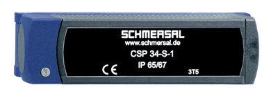
| Recommendation (actuator) |
CSP 34-S-1 |
| Recommended safety switchgear |
PROTECT PSC1 SRB-E-301ST SRB-E-201LC |
Note
| Note (General) |
Exigences pour le module de sécurité: Entrée de sécurité à 2 canaux, adaptée pour les capteurs à commutation P avec fonction NO. Le module de sécurité doit tolérer les tests fonctionnels internes des capteurs provoquant des micro-coupures cycliques de la sortie du capteur pendant max. 0,5 ms. Le module de sécurité ne doit pas être équipé d'une détection des courts-circuits transversaux. Codage du capteur de sécurité et de l'actionneur: pour activer la fonction de sécurité (codage) du CSP 34 pour la première fois, l'actionneur à appairer doit être introduit dans la zone de détection du capteur de sécurité activé. Le processus d'apprentissage automatique du code de l'actionneur est signalé par la LED rouge allumée au capteur de sécurité et le clignotement simultané de la LED jaune. Après 10 secondes, les clignotements deviennent plus brefs pour inviter l'utilisateur à couper la tension de service du capteur de sécurité pour enregistrer le code. |
Filtre de langue
Fiches techniques
Mode d'emploi et déclaration de conformité
Certificat UL
Exemple de câblage (câblage électrique)
Brochure
Bibliothèque/Library SISTEMA-VDMA
Télécharger la dernière version d'Adobe Reader
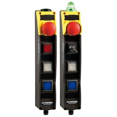
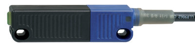
Photo du produit (photo individuelle de catalogue)
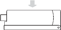
Plan d'encombrement composant de base
Principe de fonctionnement
Clipart
Courbe caractéristique


101208465 CSP 34-S-1-02
- Actuation from side
- actuator code 2
- 20 different actuator codes available
101208466 CSP 34-S-1-03
- Actuation from side
- actuator code 3
- 20 different actuator codes available
101208467 CSP 34-S-1-04
- Actuation from side
- actuator code 4
- 20 different actuator codes available
101208468 CSP 34-S-1-05
- Actuation from side
- actuator code 5
- 20 different actuator codes available
101208469 CSP 34-S-1-06
- Actuation from side
- actuator code 6
- 20 different actuator codes available
101208470 CSP 34-S-1-07
- Actuation from side
- actuator code 7
- 20 different actuator codes available
101208471 CSP 34-S-1-08
- Actuation from side
- actuator code 8
- 20 different actuator codes available
101208472 CSP 34-S-1-09
- Actuation from side
- actuator code 9
- 20 different actuator codes available
101208473 CSP 34-S-1-10
- Actuation from side
- actuator code 10
- 20 different actuator codes available
101208474 CSP 34-S-1-11
- Actuation from side
- actuator code 11
- 20 different actuator codes available
101208475 CSP 34-S-1-12
- Actuation from side
- actuator code 12
- 20 different actuator codes available
101208476 CSP 34-S-1-13
- Actuation from side
- actuator code 13
- 20 different actuator codes available
101208477 CSP 34-S-1-14
- Actuation from side
- actuator code 14
- 20 different actuator codes available
101208478 CSP 34-S-1-15
- Actuation from side
- actuator code 15
- 20 different actuator codes available
101208479 CSP 34-S-1-16
- Actuation from side
- actuator code 16
- 20 different actuator codes available
101208480 CSP 34-S-1-17
- Actuation from side
- actuator code 17
- 20 different actuator codes available
101208481 CSP 34-S-1-18
- Actuation from side
- actuator code 18
- 20 different actuator codes available
101208464 CSP 34-S-1-01
- Actuation from side
- actuator code 1
- Sensor and actuator must be ordered separately.

103009970 SRB-E-201LC
- Plug-in screw terminals with coding
- STOP 0 Function
- 1 oder 2-channel control
- Start button / Auto-start
- 2 Safety outputs 2 A
- 1 Signalling output

103009973 SRB-E-204ST
- Plug-in screw terminals with coding
- STOP 0 Function
- Monitoring of 4 sensors
- Start button / Auto-start
- 2 Safety outputs
- 4 Signalling outputs

103007672 SRB-E-301ST
- Plug-in screw terminals with coding
- STOP 0 Function
- 1 oder 2-channel control
- Start button / Auto-start
- 1 Auxiliary contact
- 3 safety contacts
101218843 RSS 36-I1-D
- Individual coding with RFID technology
- Coding level "High" according to ISO 14119
- 1 x Pre-wired cable 8-pole
- Actuation from side
- Thermoplastic enclosure
- RFID-technology for needs-based protection against tampering
- Misaligned actuation possible
- 27 mm x 108.2 mm x 35 mm
- High repeat accuracy of the switching points
- 2 short-circuit proof PNP safety outputs
- Integral cross-short, wire-breakage and external voltage monitoring of the safety cables up to the control cabinet
101216958 RSS 36-I1-D-ST
- Individual coding with RFID technology
- Coding level "High" according to ISO 14119
- 1 x connector socket M12, 8-pole
- Actuation from side
- Thermoplastic enclosure
- RFID-technology for needs-based protection against tampering
- Misaligned actuation possible
- 27 mm x 108.2 mm x 35 mm
- High repeat accuracy of the switching points
- 2 short-circuit proof PNP safety outputs
- Integral cross-short, wire-breakage and external voltage monitoring of the safety cables up to the control cabinet
Schmersal India Pvt. Ltd., Plot No - G-7/1, Ranjangaon MIDC, Tal. - Shirur, Dist.- Pune 412 220
Les données et les valeurs ont été soigneusement vérifiées. Les illustrations peuvent être différentes de l'original. Vous trouverez d'avantage de caractéristiques techniques dans les manuels d’instructions. Sous réserve de modifications techniques et errata.
Généré le: 21/04/2025 22:51
Récemment consultés