FWS 2106 C UE: 24...230V AC/DC
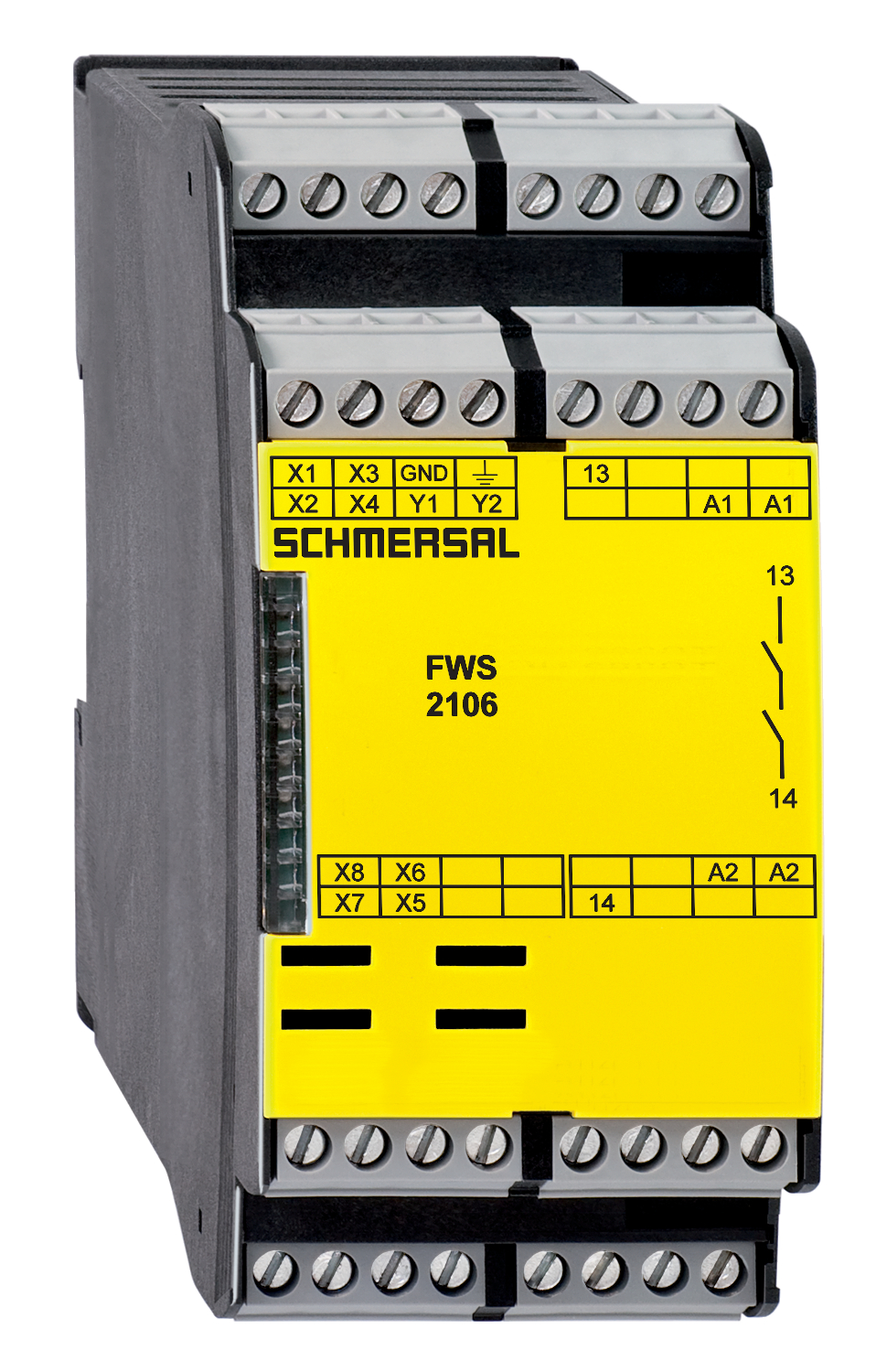
FWS 2106 C UE: 24...230V AC/DC
Downloads
- Detects standstill using 2 impulse sensor(s)
- 1 safety contact
- 2 Signalling outputs
Ordering data
| Note (Delivery capacity) |
Nicht mehr lieferbar! |
| Product type description |
FWS 2106 C UE: 24...230V AC/DC |
| Article number (order number) |
101181692 |
| EAN (European Article Number) |
4030661327006 |
| eCl@ss number, version 12.0 |
27-37-18-19 |
| eCl@ss number, version 11.0 |
27-37-18-19 |
| eCl@ss number, version 9.0 |
27-37-18-19 |
| ETIM number, version 7.0 |
EC001449 |
| ETIM number, version 6.0 |
EC001449 |
Approvals - Standards
| Certificates |
cULus |
General data
| Standards |
BG-GS-ET-20 EN IEC 62061 EN ISO 13849-1 EN IEC 60947-5-1 EN IEC 60947-5-3 EN IEC 60947-5-5 EN IEC 60204-1 EN IEC 60947-1 |
| Climatic stress |
EN 60068-2-3 BG-GS-ET-14 |
| Housing material |
Kunststoff, glasfaserverstärkter Thermoplast, belüftet |
| Gross weight |
285 g |
General data - Features
| Wire breakage detection |
Ja |
| Feedback circuit |
Ja |
| Reset edge detection |
Ja |
| Integral system diagnostics, status |
Ja |
| Number of LEDs |
1 |
| Number of undelayed semi-conductor outputs with signaling function |
2 |
| Number of safety contacts |
1 |
| Number of signalling outputs |
2 |
| Safety classification |
| Vorschriften |
EN IEC 61508 |
| Performance Level, up to |
d |
| Category |
3 |
| PFH value |
1,00 x 10⁻⁷ /h |
| Safety Integrity Level (SIL), suitable for applications in |
2 |
| Mission time |
20 Year(s) |
| Stop-Category |
0 |
Mechanical data
| Mechanical life, minimum |
20.000.000 Operations |
| Mounting |
Schnellbefestigung für Normschiene nach DIN EN 60715 |
Mechanical data - Connection technique
| Terminal designations |
IEC/EN 60947-1 |
| Termination |
starr oder flexibel Schraubanschluss M20 x 1.5 |
| Cable section, minimum |
0,2 mm² |
| Cable section, maximum |
2,5 mm² |
| Tightening torque of Clips |
0,6 Nm |
Mechanical data - Dimensions
| Width |
45 mm |
| Height |
100 mm |
| Depth |
121 mm |
Ambient conditions
| Degree of protection of the enclosure |
IP40 |
| Degree of protection of the mounting space |
IP54 |
| Degree of protection of clips or terminals |
IP20 |
| Ambient temperature |
+0 ... +55 °C |
| Storage and transport temperature |
-25 ... +70 °C |
| Resistance to vibrations |
10 ... 55 Hz, Amplitude 0,35 mm |
| Restistance to shock |
30 g / 11 ms |
Ambient conditions - Insulation values
| Rated impulse withstand voltage Uimp |
4,8 kV |
| Overvoltage category |
III |
| Degree of pollution |
2 |
Electrical data
| Type of voltage range |
AC DC |
| Rated operating voltage |
24 ... 230 VAC |
| Rated AC voltage for controls, 50 Hz, minimum |
20,4 VAC |
| Rated control voltage at AC 50 Hz, maximum |
253 VAC |
| Rated AC voltage for controls, 60 Hz, minimum |
20,4 VAC |
| Rated control voltage at AC 60 Hz, maximum |
253 VAC |
| Rated AC voltage for controls at DC minimum |
20,4 VDC |
| Rated control voltage at DC, maximum |
253 VDC |
| Electrical power consumption, maximum |
5 W |
| Contact resistance, maximum |
0,1 Ω |
| Note (Contact resistance) |
in Neuzustand |
| Material of the contacts, electrical |
Ag-Ni + Au |
Electrical data - Safe relay outputs
| Voltage, Utilisation category AC-15 |
230 VAC |
| Current, Utilisation category AC-15 |
3 A |
| Voltage, Utilisation category DC-13 |
24 VDC |
| Current, Utilisation category DC-13 |
2 A |
| Switching capacity, minimum |
10 VDC |
| Switching capacity, minimum |
10 mA |
| Switching capacity, maximum |
250 VAC |
| Switching capacity, maximum |
6 A |
Electrical data - Digital inputs
| Input signal, HIGH Signal "1" |
10 … 30 VDC |
| Input signal, LOW Signal "0" |
0 … 2 VDC |
| Conduction resistance, maximum |
40 Ω |
Integral system diagnosis (ISD)
| Note (ISD -Faults) |
Folgende Fehler werden von dem Sicherheitsbaustein erkannt und durch ISD angezeigt. |
| Faults |
Nicht-Anziehen oder Nicht-Abfallen der Sicherheitsrelais Fehler an den Eingangsschaltungen oder an den Relaisansteuerungen des Sicherheitsbausteins Ausfall der Näherungsschalter Ausfall eines Kanals der Auswertung Unterbrechung der Leitungen der induktiven Näherungsschalter |
Other data
| Note (applications) |
Sichere Stillstandsüberwachung |
Note
| Note (General) |
Induktive Verbraucher (Schütze, Relais etc.) sind durch eine geeignete Beschaltung zu entstören. |
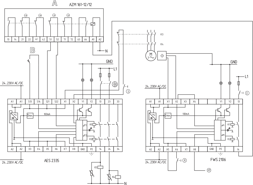
Wiring example
| Note (Wiring diagram) |
Das Schaltungsbeispiel ist bei geschlossenen Schutzeinrichtungen und im spannungslosen Zustand dargestellt. Die ISD-Tabellen (Integrierte System-Diagnose) zur Analyse der Fehlermeldungen und ihrer Ursachen sind im Anhang aufgeführt. Zur Absicherung einer Schutzeinrichtung an Anlagen mit gefährlichem Nachlauf bis zu PL d und Kategorie 3 Überwachung vom Stillstand für die Entriegelung von Sicherheitszuhaltungen. Die Sicherheitszuhaltung kann geöffnet werden, wenn der Stillstandswächter die Beendigung der Nachlaufbewegung durch die zwei induktiven Näherungsschalter erfasst hat. Durch Betätigen der Taste (E) wird die Spule der Sicherheitszuhaltung angesteuert. Geeignete p-schaltende induktive Näherungssschalter der Reihe IFL finden Sie im Schmersal Katalog "Automatisierungstechnik". Wird nur ein induktiver Näherungsschalter an den Stillstandswächter angeschlossen, müssen die Stillstandsfrequenzen gleich sein und die Eingänge X2 und X4 gebrückt werden. |
Sprachfilter
Datenblatt
Betriebsanleitung und Konformitätserklärung
UL-Zertifikat
Schaltungsbeispiel (elektr. Verdrahtung)
Download der aktuellen Version von Adobe Reader
Produktbild (Katalogeinzelphoto )
Schaltungsbeispiel
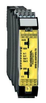
103014754 SRB-E-302FWS-TS
- 2 Safety contacts, 1 Safety Output
- Plug-in screw terminals with coding
- 1 Signalling output - status safety module
- 1 Signalling output - failure massage dynamic
- Detects standstill using 1 or 2 impulse sensors
- additional standstill signal, e.g. PLC as second input channel
- 2-channel time monitoring
Schmersal India Pvt. Ltd., Plot No - G-7/1, Ranjangaon MIDC, Tal. - Shirur, Dist.- Pune 412 220
Die genannten Daten und Angaben wurden sorgfältig geprüft. Abbildungen können vom Original abweichen. Weitere technische Daten finden Sie in der Betriebsanleitung. Technische Änderungen und Irrtümer vorbehalten.
Generiert am: 24.03.2025, 05:46
