Application: The safety switches with separate actuators are suitable for sliding, hinged and especially for removable safety guards, which need to be closed to ensure the necessary operational security. They can also be fitted on profile sections and retrofitted on existing equipment.
All class 2 safety switches shown in this chapter control category 3 or 4 to ISO 13849-1 in combination with a guard door monitor. Design and mode of operation: On the class 2 safety switches, the switching element is not physically connected to the actuator but functionally brought together or separated when switching. When the safety device is opened, the actuator is separated from the base device. During this process, the NC contacts in the safety switch are positively opened and the NO contacts closed. Enclosure rating of all the safety switches is IP 67. The safety switches can be fitted in any desired mounting position.
Application: The solenoid interlocks of the AZM series have been designed to prevent, in conjunction with the control part of a machine, e.g. fail-safe delay timers or fail-safe standstill monitors, sliding, hinged and removable safety guards such as fences, flaps or doors, from being opened before hazardous conditions (e.g. run-on movements) have been eliminated.
These solenoid interlocks are also used for cases in which the opening of a guarding device represents a non-permissible intrusion in a production process.
Design and mode of operation: 
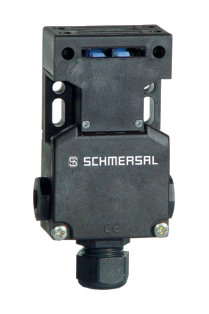
On the AZM range solenoid interlocks, the switching element with interlock is not physically connected to the actuator but functionally brought together or separated on switching. When the safety guard is opened in the unlocked condition, the actuator is separated from the base unit. During this process, the NC contacts are positively opened and the NO contacts closed.
Interlocking is carried out by means of a blocking bolt / latching bolt. This latching bolt blocks the actuator so that it cannot be withdrawn from the interlock. The machine control is only enabled when the actuator has been inserted into the interlock and the latching bolt is in blocking position. This is ensured by the contact monitoring of the latching bolt.
There are two modes of interlocking. The "Power to unlock" principle is where the locking bolt is held into position with a spring. When the de-interlocking coil is energised, the interlock is removed and the NC contacts opened. The protection equipment can be opened. For "Power to lock"1)the mode of operation is reversed.
The solenoid interlocks EX-AZM 161, 170 and 415 are fitted with protection against incorrect locking. Depending on the type of unit, an individual coding of the actuator are possible.
The solenoid interlocks can be fitted in any desired mounting position. Protection class of the solenoid interlocks is IP 54, IP 65 or IP 67.
1)In accordance with the policy of the German Technical Assessors, these interlock may only be used after a thorough evaluation of the accident risk, since the guarding device can immediately be opened on failure of the electrical power supply.
Application: Magnetic reed switches are often used to complement limit switches with plungers, rollers and swivel levers and are considered an important link to non-contact and contactless limit switches.
Application: The magnetic safety sensors are used to monitor the position of sliding, hinged or removable safety guards. Devices without integral evaluation must used only in combination with a guard door monitor up to control category 4 in accordance with ISO 13849-1 for safety tasks in accordance with IEC 60947-5-3.
The use of magnetic safety sensors is of particular advantage in cases where extremely dirty conditions can occur or high hygienic standards need to be maintained. This is provided by the simplicity of cleaning of the devices.
Another advantage is the possibility of concealed mounting behind non-magnetic materials. Working surfaces and storage areas can be arranged without the need for dust-collecting edges or other functionally required cut-outs or projections.
In applications, where a precise approach is not possible and larger tolerances are required, the magnetic safety sensors of the BNS series can also be used. Design and mode of operation: These devices comprise a multi-channel magnetic safety sensors and an actuating magnet. All magnetic safety sensors are in thermoplastic enclosures and protected to protection class IP 67 or 65.
Application: The fundamental functional characteristic of a key transfer system is that, depending on the operating state of the machine control system, the key is trapped and cannot be withdrawn either • in automatic mode (with the guard locked) in a control element (usually in a key-operated selector switch) or • in the guard locking device, namely in a lock, if the guard is open (in an electrically de-energised state).
In other words, a principle feature of the system is that the removable key is trapped either in the guard locking device or in the switch lock.
The locking device of the guard is designed in such a way that the trapped key can only be enabled if the guard is closed and locked (fail-safe). Only in this way can the key be transferred from here to the key-operated selector switch.
When the machine control system is switched on the key is trapped and cannot be removed for as long as the switch is set to ON.
If the transfer time between the opening of the key-operated selector switch and the locking of the guard is not sufficient for a hazardous machine motion to come to a standstill, a key-operated selector switch interlocking device may also be required.
Framework conditions When using the EX-SHGV safety door interlocking system it must be ensured that • the time between switching off at the control panel and access to the guard is greater than the stopping time of any hazardous motion, or that the key-operated selector switch interlocking device of the type SVE is used. • only one key is used in the trapped key system and any spare keys available are stored carefully; • the separate actuators of the EX-SHGV guard locking devices are fitted to the guard in such a way, e.g. with the non-reusable screws supplied with the equipment, that they cannot be released by simple means; • the entry throat for the separate actuator is fitted in the guard locking device in a concealed position where at all possible. This recommendation applies generally to interlocking devices with separate actuator.
Design and mode of operation: Key-operated selector switch of the SHGV/ESS type The key-operated selector switch of the SHGV/ESS type as control element to interrupt or switch off the automatic mode.
SVM interlocking device with key-operated selector switch The SVM interlocking device with key-operated selector switch is used when multiple safety guards must be operated with one key-operated selector switch.
Guard locking device Type SHGV The design of the type SHGV interlock device is based on a metal-encapsulated position switch with separate actuator, but the function of the position monitoring and locking is based exclusively on a mechanical principle of operation using the integrated lock barrel and the positively connected mechanism as well as the interaction between actuator and the articulating mechanism in the device head.
Version with a second lock barrel The version with a second lock barrel using which the operation of lock barrel 1 can be blocked if an operator needs to access a room and wishes to protect himself from unintentional start-up of the machine control system by a third party.
Application: The position switches with safety function are suitable for sliding and hinged guards, which need to be closed in order to ensure the required operational safety.
In combination with safety control modules all safety switches with class 1 shown in this chapter achieve Control Category 3 or 4 to ISO 13849-1
Further applications for positions switches class 1 are most varied positioning duties. A comprehensive range of actuating elements is available to meet the requirements of many everyday tasks. Design and mode of operation: On the position switches class 1 the guarding device and the positive break NC contact are positively linked. Enclosure rating of all the safety switches is IP 67. The safety switches can be fitted in any desired mounting position.
Pull-wire Emergency Stop switches are mounted on machines and sections of plants which cannot be protected by guards. The advantage of pull-wire switches over mushroom head Emergency-Stop push buttons is that the Emergency-Stop command can be triggered anywhere along the wire.
Application: The safety relay modules of the SRB EXi series combine tried and trusted safety technology with the requirements of explosion protection.
The inherently safe monitoring current circuits Ex-i are configured for devices of category 2GD. In this way, emergency stop command devices and protective safety door/guard monitoring can be used in areas with risk of gas and dust explosion.
Ex protection – ATEX - ATEX category (2)GD for connection
of devices from zone 1 or 21. - ATEX category 3G permits installation
of SRB EXi units in gas zone 2.
Application: The safety switches are suitable for hinged safety guards, which need to be closed to ensure the necessary operational safety.
A comprehensive range of safety switches for rotating guard systems is available to meet the most diverse requirements in actual practice.
Depending on the device configuration and design, both small doors and service flaps as well as heavy hinged guards can be mounting- and maintenance-friendly secured in machinery and plant building.
Design and mode of operation: An advantage is the integration of the cam into the switch. The requirements of EN 14119, such as positive linkage between cam and actuator as well as protection against tampering are thus fulfilled.
These safety switches are mounted with slow action.
Command and signalling devices are of great importance for the man-machine interface in the field of industrial applications. They are used, for instance, in control cabinets, control panels, in elevator construction or on conveyor and material handling plants. The manual actuation of the devices starts or stops operating sequences and functional processesThe command and signaling devices of the Ex-R series are particularly suitable for applications in explosive environments and meet the requirements of the zones 1, 2, 21 & 22. The devices are suitable for applications in rough operating conditions and feature large actuating surfaces, which means that they can be operated when the operator wears gloves.
Design and operating principle: A command and signaling device consists of a device head with mounting flange or illuminated element. The command devices are made of massive brass, the spherical cap of the indicator light or illuminated button of shock-resistant plastic. The mounting flange has two parts. The mounting of the device heads therefore can be realised independently of the mounting and wiring of the contact and illuminated elements. For each device head, 2 contact elements and 1 illuminated element can be mounted at the most. The mounting flange is designed so that both an incorrect fitting and the de-energisation of the contact and illuminated elements under high mechanical loads is effectively avoided.
Application: Belt alignment switches and slack-wire switches are suitable for use on material handling equipment. The belt alignment switch is actuated, when the conveyor belt becomes misaligned. Depending on the plant set-up, this signal can be used to switch off the machinery or plant either to provide an automatic correction of the belt alignment.
Application: Belt alignment switches and slack-wire switches are suitable for use on material handling equipment. The slack-wire switch monitor the wire tension. If the wire is properly tensioned, the switch is actuated.
In some industrial sectors, safety components must meet the requirements of explosion protection. This applies in particular to the chemicals industry, but also to many areas of the food and automobile industries, for example. Back in the 1950s, Schmersal extended its range to include products which could also be used in explosion-risk areas. In line with the European ATEX Directive 2014/34/EU and the IECEx norm, the company now offers devices for ex zones, which depending on the model, can be used in ex zones 1 or 2 (Gas Ex) or 22 (dust ex). The safety relay modules in the SR8-EXi range meet not only IECEx and INMETRO approvals but also meet international requirements for devices for EX zones.
ATEX AND IECEX CERTIFIED EX SWITCHES
The requirements for devices and protective systems for use in explosion-risk areas defined in the ATEX directives for Europe are increasingly being replaced by the internationally applicable IECEx regulations. For the user, the main change lies in the fact that the latest global standardisation amalgamates dust and gas explosion protection and provides consistent regulations. The more exacting requirements also increase the safety level. Schmersal offers safety switches and solenoid interlocks, magnetic reed switches, command and signalling devices and numerous other safety components which are both ATEX and IECEx certified.