SRB101EXi-1A
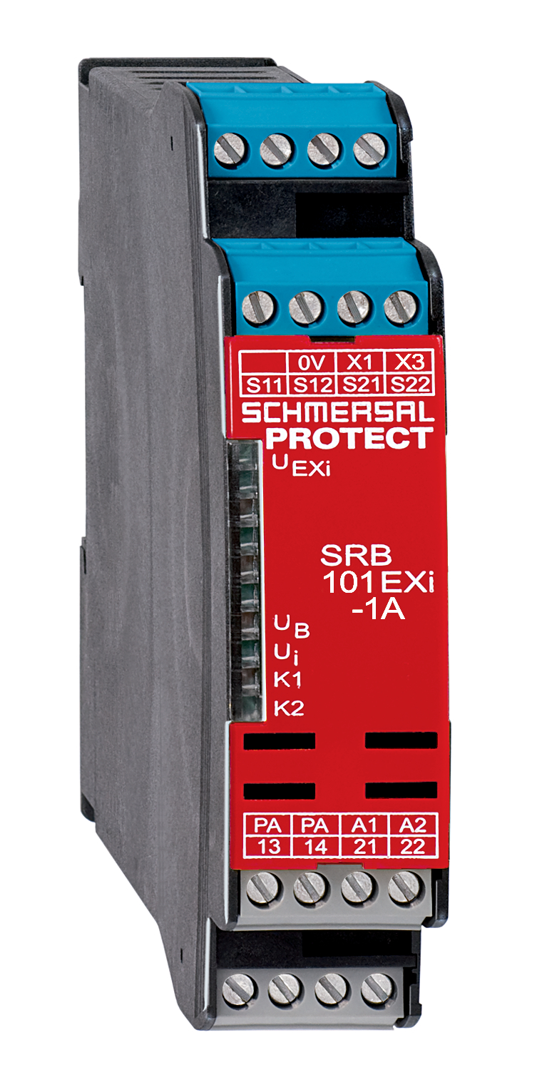
SRB101EXi-1A
- Automatic reset function
- 1 safety contact
- Suitable for signal processing of emergency stop control devices, interlocking equipment, etc
- Installation in Ex-Zone 2
Ordering data
| Note (Delivery capacity) |
Excluído do programa de fornecimento! |
| Product type description |
SRB101EXi-1A |
| Article number (order number) |
101196285 |
| EAN (European Article Number) |
4250116202379 |
| eCl@ss number, version 12.0 |
27-37-18-19 |
| eCl@ss number, version 11.0 |
27-37-18-19 |
| eCl@ss number, version 9.0 |
27-37-18-19 |
| ETIM number, version 7.0 |
EC001449 |
| ETIM number, version 6.0 |
EC001449 |
Approvals - Standards
| Certificates |
ATEX IECEx INMETRO PESO |
Explosion protection
| Explosion protection: regulations |
EN IEC 60079-0 EN 60079-11 EN IEC 60079-15 |
| Explosion protection zones |
2 |
| Explosion protection category |
3G |
| Explosion protection designation |
D II 3 G Ex nA nC IIC T5 Gc (Installation SRB, in Zone 2) D II (2) G [Ex ib Gb] IIC D II (2) D [Ex ib Db] IIIC |
General data
| Climatic stress |
EN 60068-2-78 |
| Housing material |
Plástico, termoplástico reforçado com fibra de vidro, auto-extinção de fogo |
| Gross weight |
230 g |
General data - Features
| Wire breakage detection |
Sim |
| Cross-circuit detection |
Sim |
| Feedback circuit |
Sim |
| Automatic reset function |
Sim |
| Earth connection detection |
Sim |
| Integral system diagnostics, status |
Sim |
| Number of auxiliary contacts |
1 |
| Number of LEDs |
5 |
| Number of normally closed (NC) |
2 |
| Number of safety contacts |
1 |
| Safety classification |
| Vorschriften |
EN ISO 13849-1 EN IEC 60947-5-1 EN IEC 61508 |
| Stop-Category |
0 |
| Safety classification - Relay outputs |
| Performance Level, stop 0, up to |
e |
| Category, Stop 0 |
4 |
| Diagnostic Coverage (DC) Level, Stop 0 |
≥ 99 % |
| PFH value, Stop 0 |
2,00 x 10⁻⁸ /h |
| Safety Integrity Level (SIL), Stop 0, suitable for applications in |
3 |
| Mission time |
15 Year(s) |
| Common Cause Failure (CCF), minimum |
65 |
Mechanical data
| Mechanical lifetime, minimum |
10.000.000 Operations |
| Mounting |
Fixação rápida para perfil normalizado segundo a DIN EN 60715 |
Mechanical data - Connection technique
| Terminal designations |
IEC/EN 60947-1 |
| Cable section, minimum |
0,25 mm² |
| Cable section, maximum |
2,5 mm² |
| Tightening torque of Clips |
0,6 Nm |
| Allowed type of cable |
Rígido de um fio Flexível |
| Terminal (mechanical) |
1000075113 |
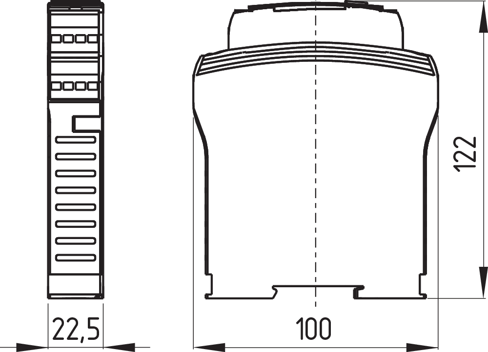
Mechanical data - Dimensions
| Width |
22,5 mm |
| Height |
100 mm |
| Depth |
121 mm |
Ambient conditions
| Degree of protection of the enclosure |
IP40 |
| Degree of protection of the installation space |
IP54 |
| Degree of protection of clips or terminals |
IP20 |
| Ambient temperature |
-25 ... +60 °C |
| Storage and transport temperature |
-40 ... +85 °C |
| Resistance to vibrations |
10 ... 55 Hz, amplitude 0,35 mm |
| Restistance to shock |
10 g / 11 ms |
Ambient conditions - Insulation values
| Rated impulse withstand voltage Uimp |
4 kV |
| Overvoltage category |
III |
| Degree of pollution |
2 |
Electrical data
| Operating voltage |
24 VDC -10 % / +20 % |
| Ripple voltage |
10 % |
| Current consumption |
57 mA |
| Rated operating voltage |
24 VDC |
| Rated AC voltage for controls at DC minimum |
20,4 VDC |
| Rated control voltage at DC, maximum |
28,8 VDC |
| Utilisation category AC-15 |
230 VAC |
| Utilisation category AC-15 |
2 A |
| Utilisation category DC-13 |
24 VDC |
| Utilisation category DC-13 |
2 A |
| Electrical power consumption |
3 W |
| Contact resistance, maximum |
0,1 Ω |
| Note (Contact resistance) |
em perfeitas condições |
| Drop-out delay in case of power failure, typically |
20 ms |
| Drop-out delay in case of "emergency stop", maximum |
20 ms |
| Pull-in delay at automatic start, maximum, typically |
300 ms |
| Pull-in delay at RESET, typically |
20 ms |
| Material of the contacts, electrical |
AgSn0. auto limpante, contactos com guia positivo |
Electrical data - Digital inputs
| Conduction resistance, maximum |
30 Ω |
Electrical data - Electromagnetic compatibility (EMC)
| EMC rating |
Diretiva CEM |
Other data
| Note (applications) |
Sensor de segurança Dispositivo de segurança Botão "Paragem de Emergência" Interruptor de emergência - acionamento por cabo |
Note
| Note (General) |
Cargas indutivas (contactores, reles, etc.) deverão ser absorvidas por meio de circuitos apropriados |
Wiring example
| Note (Wiring diagram) |
O exemplo de comutação é o do dispositivo de segurança fechado mostrando o estado sem a presença de tensão. Supervisão de 1 dispositivos de segurança utilizando um sensor de segurança magnético da linhas BNS em cada dispositivo Utilizando-se somente um relê externo ou um disjuntor para comutar a carga, o sistema pode ser enquadrado na categoria de comando 3 de acordo com ISO 13849-1, quando a "exclusão da falha do disjuntor externo" puder ser documentada / registrada como por exemplo na utilização de um contactor confiável, superdimensionado. Um segundo contactor leva a uma elevação da segurança através de uma desconexão redundante da carga. Um segundo contactor leva a uma elevação da segurança através de uma desconexão redundante da carga. Para proteção de um dispositivo de segurança até a PL e e categoria 4 O circuito de retorno supervisiona a posição dos disjuntores KA e KB. Arranque automático: A programação de arranque automático é efetuada através da integração do circuito de retorno nos terminais X1/X2. Quando o circuito de retorno não é necessário, ele pode ser substituído por uma ponte. |
Filtro de idioma
Ficha técnica
Manual de instruções e Declaração de conformidade
Certificação INMETRO
PESO-Zertifikat
Folheto
Faça download da versão mais recente do Adobe Reader
Foto do produto (foto individual do catálogo )
Desenho dimensional componente básico
Símbolo (norma técnica)

Exemplo de ligação


103037576 SRB101EXi-1A
- Automatic reset function
- Reset with trailing edge
- 1 safety contact
- Suitable for signal processing of emergency stop control devices, interlocking equipment, etc
- Installation in Ex-Zone 2
| EU Declaration of Conformity |  |
| Original | K.A. Schmersal GmbH & Co. KG Möddinghofe 30 42279 Wuppertal Germany Internet: www.schmersal.com |
| Declaration: | We hereby certify that the hereafter described components both in their basic design and construction conform to the applicable European Directives. |
| Name of the component: | SRB101EXi-1A |
| Type: | See ordering code |
| Marking: | D II 3 (2) G Ex ec nC [ib Gb] IIC T5 Gc D II (2) D [Ex ib Db] IIIC |
| Description of the component: | Safety-monitoring module for emergency stop circuits and guard door monitoring |
| Relevant Directives: | Machinery Directive | 2006/42/EC |
| EMC-Directive | 2014/30/EU | |
| Explosion Protection Directive (ATEX) | 2014/34/EU | |
| RoHS-Directive | 2011/65/EU |
| Applied standards: | EN IEC 60079-0:2018 EN 60079-7:2015 EN IEC 60079-7:2015 / A1:2018 EN 60079-11:2012 EN IEC 60079-15:2019 EN 60947-5-1:2017 + AC:2020 EN ISO 13849-1:2015 EN ISO 13849-2:2012 |
| Notified body for certification of the QA system in accordance with Appendix X in accordance with 2006/42/EC, Appendix IV in accordance with 2014/34/EU and for ATEX certification: | TÜV Rheinland Industrie Service GmbH Am Grauen Stein, 51105 Köln ID n°: 0035 |
| Type Examination Certificate: | TÜV 22 ATEX 8837 X |
| This certificate refers only to the certification of the products in accordance with the Explosion Protection Directive 2014/34/EU (ATEX). Product conformity in accordance with the Machinery Directive 2006/42/EC is declared by the manufacturer under its own responsibility. |
| Person authorised for the compilation of the technical documentation: | Oliver Wacker Möddinghofe 30 42279 Wuppertal |
| Place and date of issue: | Wuppertal, October 30, 2024 |
 |
| Authorised signature Philip Schmersal Managing Director |
Schmersal India Pvt. Ltd., Plot No - G-7/1, Ranjangaon MIDC, Tal. - Shirur, Dist.- Pune 412 220
Os dados e informações anteriores foram verificados cuidadosamente. As imagens podem ser diferentes do original. Mais informações técnicas podem ser encontradas nos manuais de instruções. Sujeito a modificações técnicas e erros.
Gerado em 23/08/2025 23:17