AES 2336 UE: 24...230V AC/DC

AES 2336 UE: 24...230V AC/DC
- Monitoring of BNS range magnetic safety sensors
- 3 safety contacts, STOP 0
- 2 Signalling outputs
Ordering data
| Note (Delivery capacity) |
Elde mevcut değil! |
| Product type description |
AES 2336 UE: 24...230V AC/DC |
| Article number (order number) |
101181678 |
| EAN (European Article Number) |
4030661323091 |
| eCl@ss number, version 12.0 |
27-37-18-19 |
| eCl@ss number, version 11.0 |
27-37-18-19 |
| eCl@ss number, version 9.0 |
27-37-18-19 |
| ETIM number, version 7.0 |
EC001449 |
| ETIM number, version 6.0 |
EC001449 |
| Available until |
31.12.2024 |
Approvals - Standards
| Certificates |
cULus |
General data
| Standards |
BG-GS-ET-14 BG-GS-ET-20 EN IEC 62061 EN IEC 60947-5-1 EN IEC 60947-5-3 EN IEC 60947-5-5 EN IEC 61508 EN IEC 60204-1 EN IEC 60947-1 |
| Climatic stress |
EN 60068-2-3 BG-GS-ET-14 |
| Housing material |
Plastik, fiber cam takviyeli termoplastik |
| Gross weight |
300 g |
General data - Features
| Wire breakage detection |
Evet |
| Cross-circuit detection |
Evet |
| Feedback circuit |
Evet |
| Automatic reset function |
Evet |
| Start-up test |
Evet |
| Reset after disconnection of supply voltage |
Evet |
| Integral system diagnostics, status |
Evet |
| Number of LEDs |
1 |
| Number of normally closed (NC) |
2 |
| Number of normally open (NO) |
1 |
| Number of undelayed semi-conductor outputs with signaling function |
2 |
| Number of safety contacts |
3 |
| Number of signalling outputs |
2 |
| Safety classification |
| Vorschriften |
EN ISO 13849-1 EN IEC 61508 |
| Stop-Category |
0 |
| Safety classification - Relay outputs |
| Performance Level, up to |
d |
| Category |
3 |
| PFH value |
1,00 x 10⁻⁷ /h |
| Notice |
Maks. 50.000 anahtarlama çevrimi/yıla kadar ve maks. %80 kontak yükünde |
| Safety Integrity Level (SIL), suitable for applications in |
2 |
| Mission time |
20 Year(s) |
Mechanical data
| Mechanical life, minimum |
20.000.000 Operations |
| Mounting |
EN 60715 e uygun standart DIN rayının üzerine kilitlenir |
Mechanical data - Connection technique
| Terminal designations |
IEC/EN 60947-1 |
| Termination |
Sabit ya da esnek Vida bağlantısı M20 x 1.5 |
| Cable section, minimum |
0,25 mm² |
| Cable section, maximum |
2,5 mm² |
| Tightening torque of Clips |
0,6 Nm |
Mechanical data - Dimensions
| Width |
45 mm |
| Height |
100 mm |
| Depth |
121 mm |
Ambient conditions
| Degree of protection of the enclosure |
IP40 |
| Degree of protection of the mounting space |
IP54 |
| Degree of protection of clips or terminals |
IP20 |
| Ambient temperature |
+0 ... +55 °C |
| Storage and transport temperature |
-25 ... +70 °C |
| Resistance to vibrations |
10...55 Hz, Genlik 0.35 mm, ± 15 % |
| Restistance to shock |
30 g / 11 ms |
Ambient conditions - Insulation values
| Rated impulse withstand voltage Uimp |
4 kV |
| Overvoltage category |
III |
| Degree of pollution |
2 |
Electrical data
| Frequency range |
50 Hz 60 Hz |
| Type of voltage range |
AC DC |
| Thermal test current |
6 A |
| Rated operating voltage |
24 ... 230 VAC |
| Rated AC voltage for controls, 50 Hz, minimum |
20,4 VAC |
| Rated control voltage at AC 50 Hz, maximum |
253 VAC |
| Rated AC voltage for controls, 60 Hz, minimum |
20,4 VAC |
| Rated control voltage at AC 60 Hz, maximum |
253 VAC |
| Rated AC voltage for controls at DC minimum |
20,4 VDC |
| Rated control voltage at DC, maximum |
253 VDC |
| Electrical power consumption |
5 W |
| Contact resistance, maximum |
0,1 Ω |
| Note (Contact resistance) |
yeni durumda |
| Drop-out delay in case of power failure, typically |
80 ms |
| Drop-out delay in case of emergency, typically |
20 ms |
| Pull-in delay at automatic start, maximum, typically |
100 ms |
| Pull-in delay at RESET, typically |
20 ms |
| Material of the contacts, electrical |
Ag-Ni 10 ve 0.2 µm altın kaplama |
Electrical data - Safe relay outputs
| Voltage, Utilisation category AC-15 |
230 VAC |
| Current, Utilisation category AC-15 |
3 A |
| Voltage, Utilisation category DC-13 |
24 VDC |
| Current, Utilisation category DC-13 |
2 A |
| Switching capacity, minimum |
10 VDC |
| Switching capacity, minimum |
10 mA |
| Switching capacity, maximum |
250 VAC |
| Switching capacity, maximum |
8 A |
Electrical data - Digital inputs
| Input signal, HIGH Signal "1" |
10 … 30 VDC |
| Input signal, LOW Signal "0" |
0 … 2 VDC |
| Conduction resistance, maximum |
40 Ω |
Electrical data - Digital Output
| Voltage, Utilisation category DC-12 |
24 VDC |
| Current, Utilisation category DC-12 |
0,1 A |
Electrical data - Relay outputs (auxiliary contacts)
| Switching capacity, maximum |
24 VDC |
| Switching capacity, maximum |
2 A |
Electrical data - Electromagnetic compatibility (EMC)
| EMC rating |
EMC-Directive |
Integral system diagnosis (ISD)
| Note (ISD -Faults) |
Aşağıdaki hatalar emniyetli kontrol modülleri tarafından kaydedilmiştir ve ISD ile belirtilir. |
| Faults |
Emniyet rölesi devreye girmede veya devre dışı kalmada başarısız Kapı kontaktları kapatmada ve açmada başarısız Anahtar bağlantılarının çapraz bağlantısı veya kısa devre kontrolü Anahtar bağlantılarının kesintisi Emniyetli kontrol modülünün giriş devreleri veya röle kontrol devreleri üzerinde arıza Emniyet rölesi üzerinde işlevsel arıza veya arıza göstermede başarısız |
Other data
| Note (applications) |
Güvenlik sensörü Koruma sistemi |
Note
| Note (General) |
Inductive loads (e.g. contactors, relays, etc.) are to be suppressed by means of a suitable circuit. |
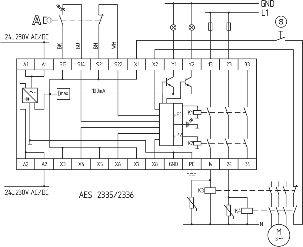
Wiring example
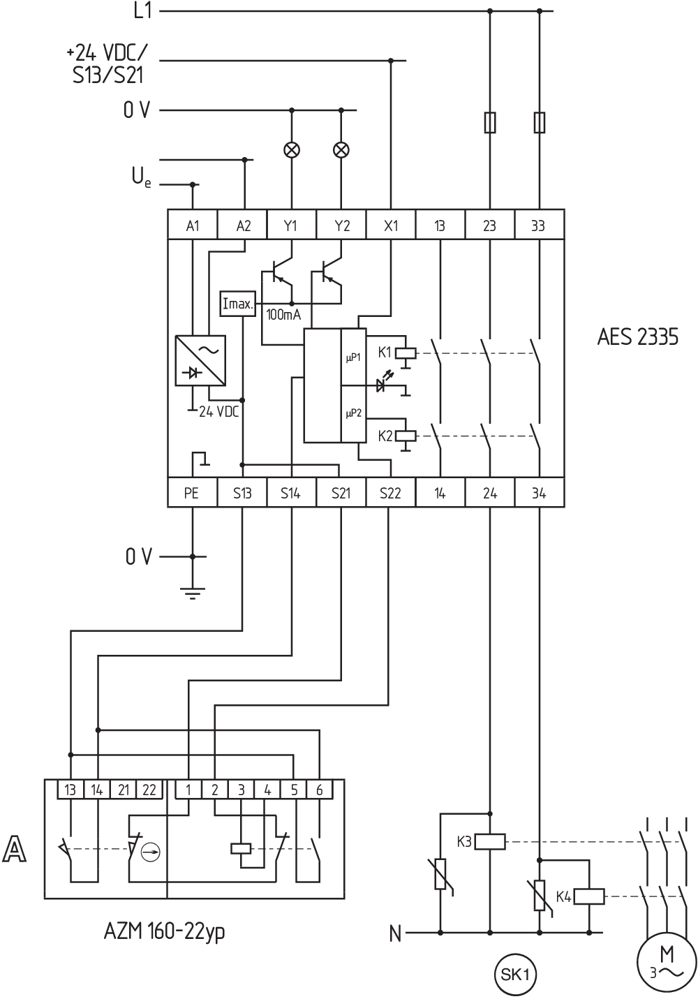
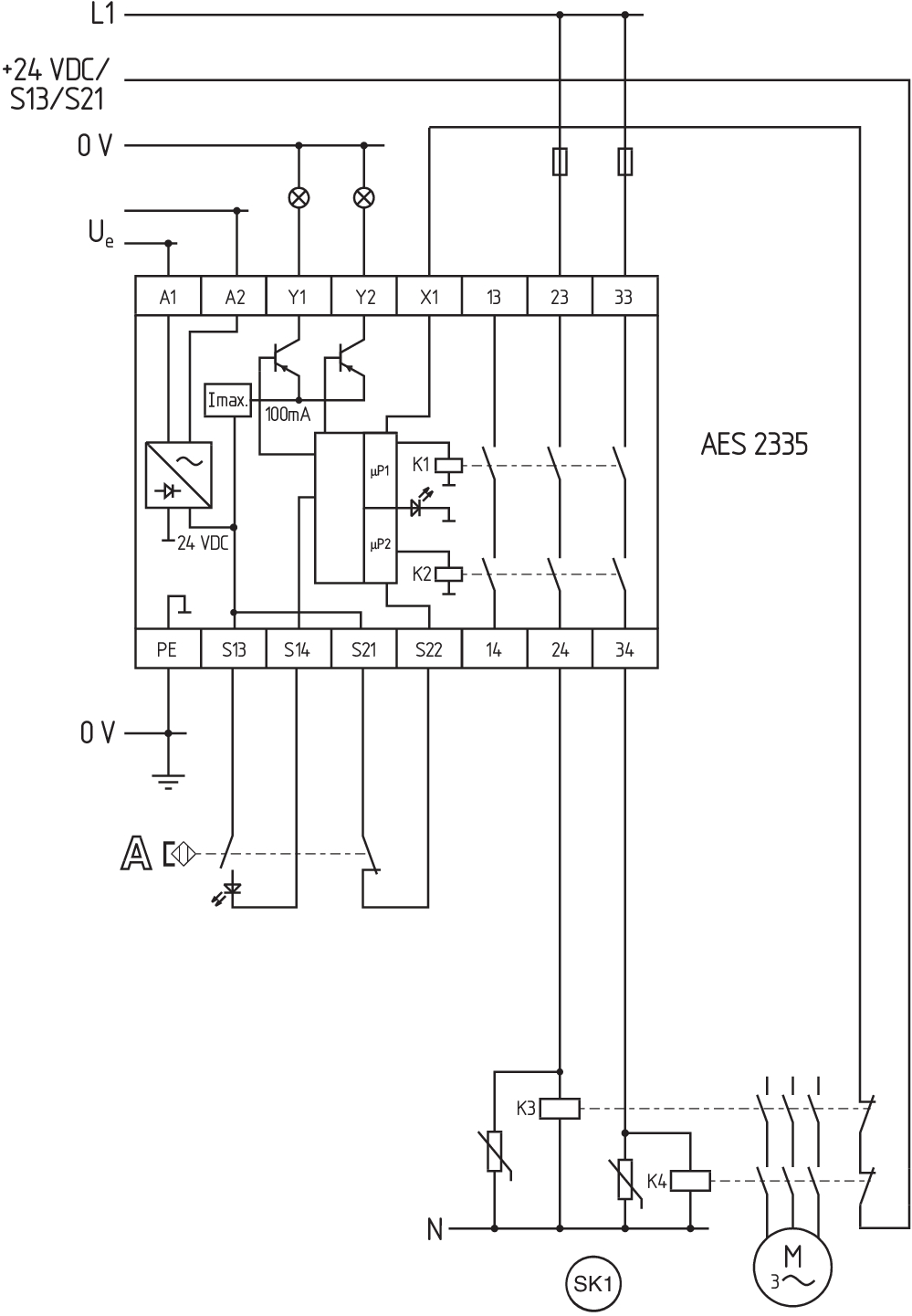
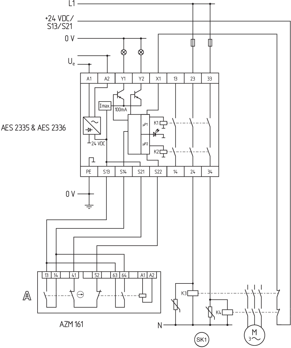
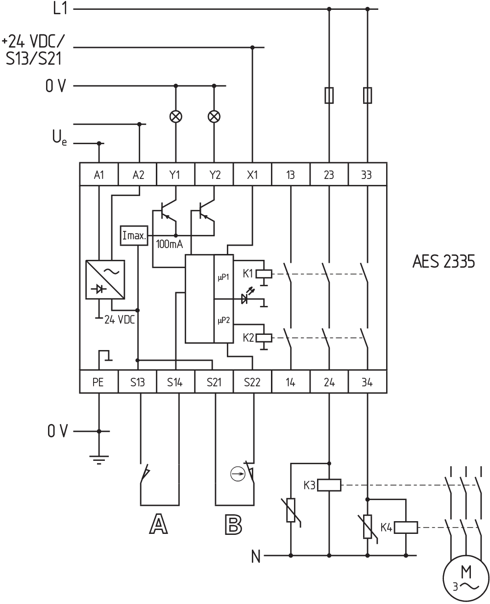
| Note (Wiring diagram) |
The wiring diagram is shown with guard doors closed and in de-energised condition. To secure a guard door up to PL d and Category 3 The ISD tables (Intergral System Diagnostics) for analysis of the fault indications and their causes are shown in the appendix. Start push button: A start push button (NO) can optionally be connected into the feedback circuit. With the guard door closed, the enabling paths are then not closed until the start push button has been operated. Modification for 2 NC contacts: The safety monitoring module can be modified to monitor two NC contacts by bridging the terminals X3 and X4. In this configuration, the short-circuit detection becomes inoperative. Inversion of the output function: By establishing a bridge between X5 and X6, the output function of the additional outputs can be altered. This control can also be realised when e.g. a PLC is running (24 VDC at terminal X6). Expansion of the enable delay time. The enable delay time can be increased from X7 s to X8 s by mounting a jumper connection between the terminals 0,1 and 1. Monitoring a guard door using 2 position switches with safety function. The NC contact A must have positive break when the guard door is opened. Category 3 to ISO 13849-1 can also be achieved using only one safety switch with one NO and one NC contact. Exclusion of faults due to breakage or loosening of the actuating element or the actuating head as well as releasing, dismantling. The feedback circuit monitors the position of the positive-guided NC contacts of the contactors K3 and K4. If neither start button nor feedback circuit are connected, a jumper connection must be mounted between X1 and X2. |
Dil filtresi
Veri sayfası
Çalışma Talimatları ile Uygunluk beyanı
UL Sertifikası
Kablo döşeme örneği (elektr. kablolama)
Kuvvet-hareket şeması
SISTEMA-VDMA kütüphanesi
Adobe Reader’ın son sürümünü indirin
Ürün resmi (katalog özel fotoğraf)
Kablo döşeme örneği
Kablo döşeme örneği
Kablo döşeme örneği
Kablo döşeme örneği
Kablo döşeme örneği

103009970 SRB-E-201LC
- Plug-in screw terminals with coding
- STOP 0 Function
- 1 oder 2-channel control
- Start button / Auto-start
- 2 Safety outputs 2 A
- 1 Signalling output

103007672 SRB-E-301ST
- Plug-in screw terminals with coding
- STOP 0 Function
- 1 oder 2-channel control
- Start button / Auto-start
- 1 Auxiliary contact
- 3 safety contacts
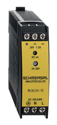
103015923 ML30.241-70
- 1-phase DIN rail power supplies
- AC 100-240V Wide-range input
- DC Output 24-28VDC / 1,3-1,1A / 30W
- Efficiency up to 89,4%
- Width only 22,5mm
| EU Declaration of Conformity |  |
| Original | K.A. Schmersal GmbH & Co. KG Möddinghofe 30 42279 Wuppertal Germany Internet: www.schmersal.com |
| Declaration: | We hereby certify that the hereafter described components both in their basic design and construction conform to the applicable European Directives. |
| Name of the component: | AES 1135/1136 AES 1165/1165-2250 AES 1235/1236 AES 1265/1265-2250 AES 2135 AES 2335/2365 AES 2535 |
| Type: | See ordering code |
| Description of the component: | Safety-monitoring module |
| Relevant Directives: | Machinery Directive | 2006/42/EC |
| EMC-Directive | 2014/30/EU | |
| RoHS-Directive | 2011/65/EU |
| Applied standards: | DIN EN 60947-5-1:2018 DIN EN ISO 13849-1:2016 DIN EN ISO 13849-2:2013 |
| Notified body, which approved the full quality assurance system, referred to in Appendix X, 2006/42/EC: | TÜV Rheinland Industrie Service GmbH Am Grauen Stein, 51105 Köln ID n°: 0035 |
| Person authorised for the compilation of the technical documentation: | Oliver Wacker Möddinghofe 30 42279 Wuppertal |
| Place and date of issue: | Wuppertal, January 31, 2024 |
 |
| Authorised signature Philip Schmersal Managing Director |
Schmersal India Pvt. Ltd., Plot No - G-7/1, Ranjangaon MIDC, Tal. - Shirur, Dist.- Pune 412 220
Veriler ve ayrıntılar dikkatli bir şekilde kontrol edilmişlerdir. Görüntüler orijinalden farklı olabilir. Daha fazla teknik veri kılavuzda bulunabilir. Teknik değişiklikler ve hatalar olabilir.
Udarbejdet d. 26.02.2025 17:22