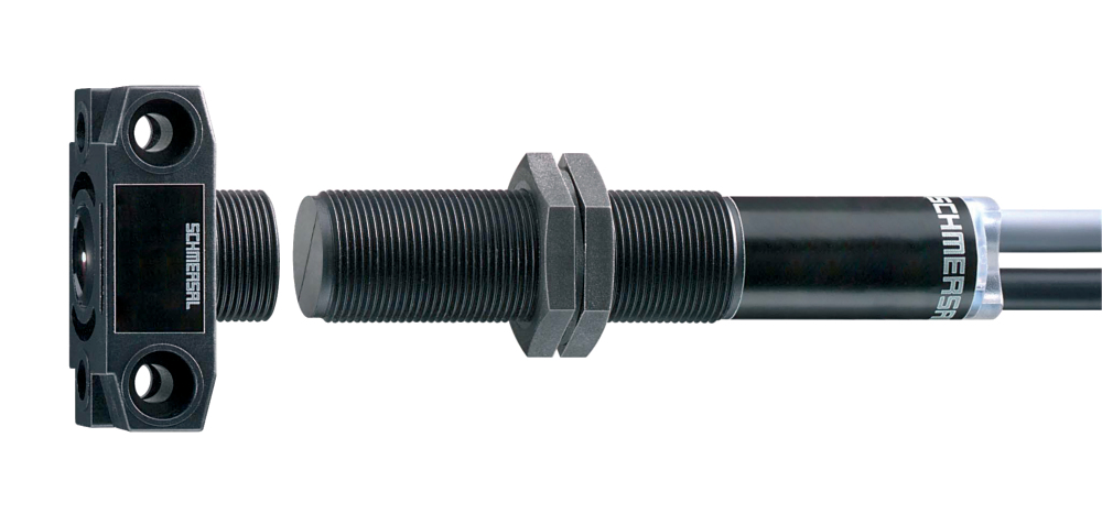
EX-CSS 8-180-2P+D-M-L-3G/D 5,0M
EX-CSS 8-180-2P+D-M-L-3G/D 5,0M
- Pre-wired cable 7-pole
- Comfortable diagnostics through sensor LED and electronic signalling output
- Thermoplastic enclosure
- Electronic contact-free, coded system
- Ø M18
- Misaligned actuation possible
- High repeat accuracy of the switching points
- Max. length of the sensor chain 200 m
- Early warning when operating near the limit of the sensor's hysteris range
- Self-monitoring series-wiring of 16 sensors
- 2 short-circuit proof PNP safety outputs
- Explosion protection for ATEX Zones 2 and 22
Ordering data
| Product type description |
EX-CSS 8-180-2P+D-M-L-3G/D 5,0M |
| Article number (order number) |
101190269 |
| EAN (European Article Number) |
4030661349039 |
| eCl@ss number, version 12.0 |
27-27-46-01 |
| eCl@ss number, version 11.0 |
27-27-24-03 |
| eCl@ss number, version 9.0 |
27-27-24-03 |
| ETIM number, version 7.0 |
EC001829 |
| ETIM number, version 6.0 |
EC001829 |
Approvals - Standards
| Certificates |
TÜV UKCA ATEX (Konformitätserklärung) |
Explosion protection
| Explosion protection: regulations |
EN IEC 60079-0 EN IEC 60079-15 EN 60079-31 |
| Explosion protection zones |
2 22 |
| Explosion protection category |
3G 3D |
| Explosion protection designation |
D II 3G Ex nA IIB T6 Gc X D II 3G Ex nA IIC T6 Gc X D II 3D Ex tc IIIC T70°C Dc X |
| Manufacturer declaration |
ATEX Zone 2 and 22 |
General data
| Working principle |
inductive |
| Housing construction form |
Cylinder, thread |
| Installation conditions (mechanical) |
not flush |
| Sensor topology |
Sensor for series wiring |
| Housing material |
Glass-fibre, reinforced thermoplastic |
| Active area |
Glass-fibre, reinforced thermoplastic |
| Material of the nuts |
Glass-fibre, reinforced thermoplastic |
| Reaction time, maximum |
30 ms |
| Duration of risk, maximum |
30 ms |
| Gross weight |
340 g |
General data - Features
| Short circuit detection |
Yes |
| Cross-circuit detection |
Yes |
| Safety functions |
Yes |
| Integral system diagnostics, status |
Yes |
| Number of semi-conductor outputs with signaling function |
1 |
| Number of fail-safe digital outputs |
2 |
| Number of series-wiring of sensors |
16 |
| Safety classification |
| Vorschriften |
EN ISO 13849-1 EN IEC 61508 |
| Performance Level, up to |
e |
| Category |
4 |
| PFH value |
2.50 x 10⁻⁹ /h |
| Safety Integrity Level (SIL), suitable for applications in |
3 |
| Mission time |
20 Year(s) |
Mechanical data
| Impact energy, maximum |
2 J |
| Tightening torque of nuts, maximum |
3 Nm |
Mechanical data - Switching distances
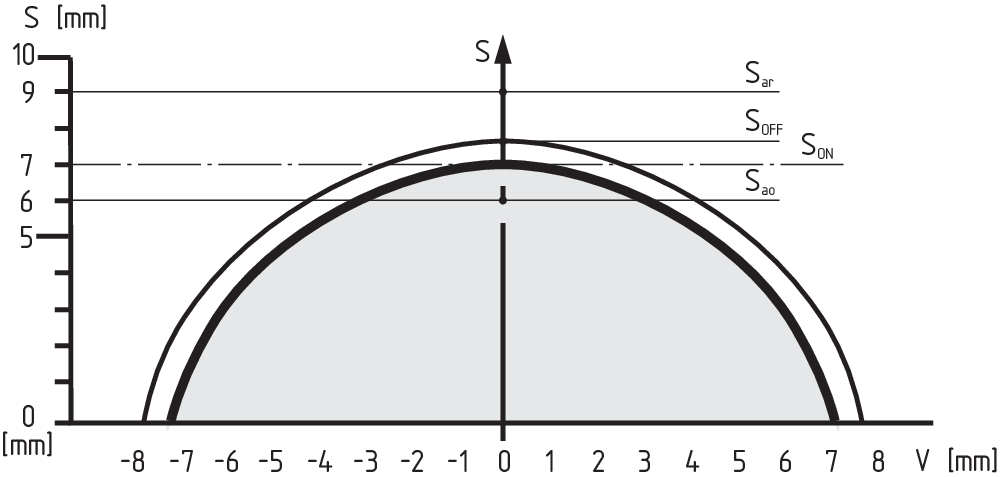
| Switch distance, typical |
8 mm |
| Assured switching distance "ON" Sao |
7 mm |
| Assured switching distance "OFF" Sar |
10 mm |
| Note (switching distance) |
All switching distances in accordance EN IEC 60947-5-3 |
| Hysteresis (Switching distance), maximum |
0.7 mm |
| Repeat accuracy R |
0.2 mm |
Mechanical data - Connection technique
| Length of cable |
5 m |
| Termination |
cable |
| Terminal connector, Output |
7-pole |
| Number of cable wires |
7 |
| Wire cross-section |
0.25 mm2 |
| Wire cross-section |
23 AWG |
Mechanical data - Dimensions
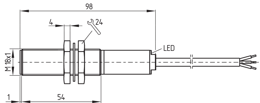
| ISO thread of the sensor |
M18 |
| width across flats |
24 BK |
| Length of sensor |
92 mm |
Ambient conditions
| Degree of protection |
IP65 IP67 |
| Ambient temperature |
-25 ... +40 °C |
| Storage and transport temperature |
-25 ... +85 °C |
| Resistance to vibrations |
10 … 55 Hz, amplitude 1 mm |
| Restistance to shock |
30 g / 11 ms |
| Protection class |
II |
Ambient conditions - Insulation values
| Rated insulation voltage Ui |
32 VDC |
| Rated impulse withstand voltage Uimp |
0.8 kV |
| Overvoltage category |
III |
| Degree of pollution |
3 |
Electrical data
| Operating voltage |
24 VDC -15 % / +10 % |
| No-load supply current I0, typical |
50 mA |
| Rated operating voltage |
24 VDC |
| Operating current |
1,000 mA |
| Switching frequency, approx. |
3 Hz |
| Utilisation category DC-12 |
24 VDC / 0.05 A |
Electrical data - Safety digital outputs
| Design of control elements |
p-type |
| Voltage drop Ud, maximum |
0.5 V |
| Leakage current Ir, maximum |
0.5 mA |
| Voltage, Utilisation category DC-12 |
24 VDC |
| Current, Utilisation category DC-12 |
0.5 A |
| Voltage, Utilisation category DC-13 |
24 VDC |
| Current, Utilisation category DC-13 |
0.5 A |
Electrical data - Digital Output
| Design of control elements |
p-type |
Electrical data - Diagnostic outputs
| Voltage drop Ud, maximum |
4 V |
| Voltage, Utilisation category DC-12 |
24 VDC |
| Current, Utilisation category DC-12 |
0.05 A |
| Voltage, Utilisation category DC-13 |
24 VDC |
| Current, Utilisation category DC-13 |
0.05 A |
Status indication
| Note (LED switching conditions display) |
Multi-coloured LED: Green, Red, Yellow |
Pin assignment
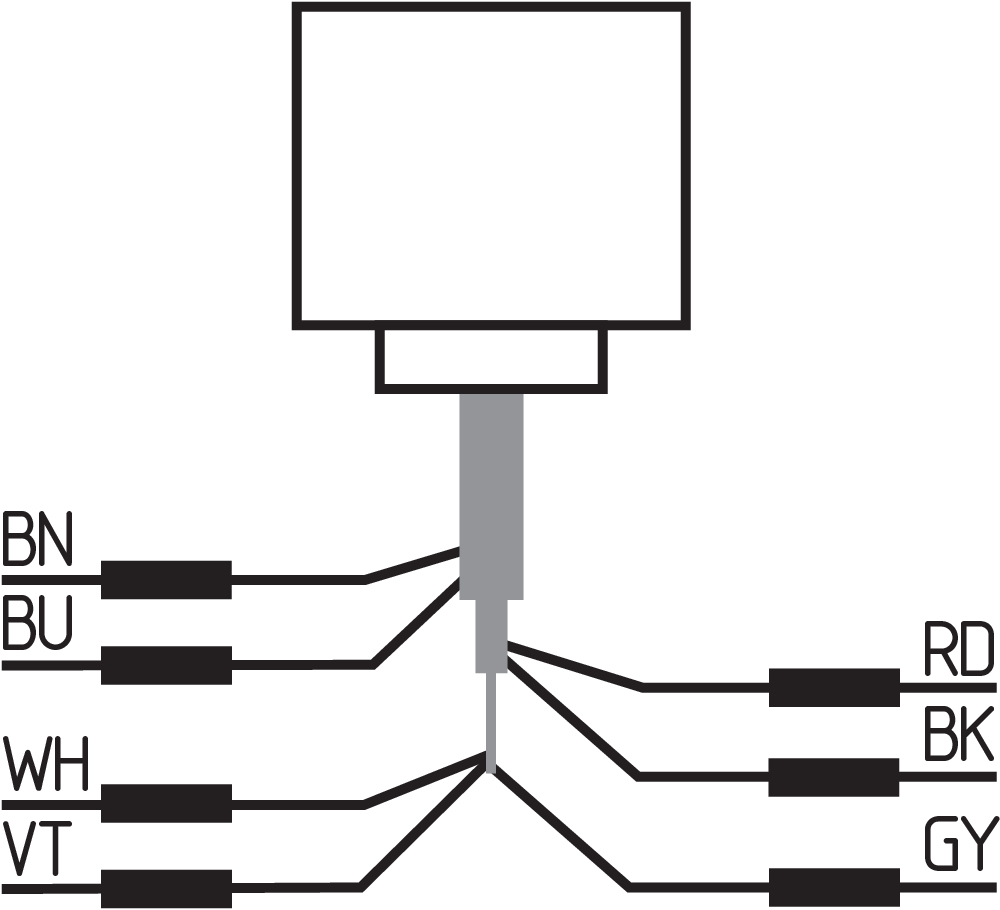
| PIN 1 |
A1 Ue Brown |
| PIN 2 |
Y2 Safety output 2 red |
| PIN 3 |
A2 GND Blue |
| PIN 4 |
Y1 Safety output 1 Black |
| PIN 5 |
X1 Safety input 1 violet |
| PIN 6 |
X2 Safety input 2 White |
| PIN 7 |
Signalling output Grey |
Scope of delivery
| Scope of delivery |
Actuator must be ordered separately. |
| Scope of delivery of mounting material |
2x nuts M18 x 1 |
Accessory
| Recommendation (actuator) |
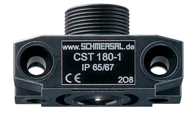
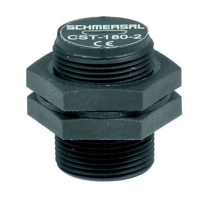
CST 180-1 CST 180-2 |
Note
| Note (General) |
Series-wiring of sensors: 16 safety sensors can be switched in series with self-monitoring. In this case, the dual-channel output of a sensor is switched to/inserted into the input of the next sensor. This does not affect the category 4 in accordance with EN ISO 13849-1. The voltage drop over a long sensor chain should be taken into account when planning cable routing. Operating voltage, cross-section and length of the cable, temperature, number of sensors connected, but also the input load of the control monitor all affect the voltage drop over the sensor chain. |
Language filter
Datasheet
Operating instructions and Declaration of conformity
TÜV certification
UKCA certificate
Wiring example (electr. wiring)
Brochure
SISTEMA-VDMA library
Download the latest version of Adobe Reader
Product picture (catalogue individual photo)
Dimensional drawing basic component
Diagram
Characteristic curve
Family picture (group photo)
| UK Declaration of Conformity |  |
| Company: | K.A. Schmersal GmbH & Co. KG Möddinghofe 30 42279 Wuppertal Germany Internet: www.schmersal.com |
| Declaration: | We hereby, under sole responsibility, certify that the hereafter described components both in their basic design and construction conform to the relevant statutory requirements, regulations and designated standards of the United Kingdom. |
| Name of the component: | EX-CSS 8-180 |
| Type: | See ordering code |
| Marking: | D II 3G Ex nA IIC T6 Gc X D II 3D Ex tc IIIC T70°C Dc X |
| Description of the component: | Non-contact safety sensor |
| Relevant legislation: | Supply of Machinery (Safety) Regulations | 2008 |
| Electromagnetic Compatibility Regulations | 2016 | |
| Equipment and Protective Systems intended for use in Potentially Explosive Atmospheres Regulations | 2016 | |
| The Restriction of the Use of Certain Hazardous Substances in Electrical and Electronic Equipment Regulations | 2012 |
| Designated standards: | EN 60947-5-3:2013, EN ISO 14119:2013, EN ISO 13849-1:2015, EN 61508 parts 1-7:2010, EN IEC 60079-0:2018, EN IEC 60079-15:2019, EN 60079-31:2014 |
| Approved body for Type Examination: | TÜV Rheinland Industrie Service GmbH Am Grauen Stein, 51105 Köln ID n°: 0035 |
| Type examination certificate: | 01/205/5874.00/21 |
| The conformity assessment procedure for explosion protection was carried out in accordance with Article 13 of Directive 2014/34/EU, under the responsibility of the manufacturer K.A. Schmersal GmbH & Co. KG. |
| UK-Importer / Person authorised for the compilation of the technical documentation: | Schmersal UK Ltd. Paul Kenney Unit 1, Sparrowhawk Close Enigma Business Park Malvern, Worcestershire, WR14 1GL |
| Place and date of issue: | Wuppertal, August 12, 2022 |
 |
| Authorised signature Philip Schmersal Managing Director |
| EU Declaration of Conformity |  |
| Original | K.A. Schmersal GmbH & Co. KG Möddinghofe 30 42279 Wuppertal Germany Internet: www.schmersal.com |
| Declaration: | We hereby certify that the hereafter described components both in their basic design and construction conform to the applicable European Directives. |
| Name of the component: | EX-CSS 180 |
| Type: | See ordering code |
| Marking: | D II 3G Ex nA IIC T6 Gc X |
| D II 3D Ex tc IIIC T70°C Dc X |
| Description of the component: | Non-contact safety sensor |
| Relevant Directives: | Machinery Directive | 2006/42/EC |
| EMC-Directive | 2014/30/EU | |
| Explosion Protection Directive (ATEX) | 2014/34/EU | |
| RoHS-Directive | 2011/65/EU |
| Applied standards: | DIN EN 60947-5-3:2014 EN 60079-0:2012 + A11:2013 EN 60079-15:2010 EN 60079-31:2014 |
| Notified body, which approved the full quality assurance system, referred to Appendix IV, 2014/34/EU: | TÜV Rheinland Industrie Service GmbH Am Grauen Stein, 51105 Köln ID n°: 0035 |
| Person authorised for the compilation of the technical documentation: | Oliver Wacker Möddinghofe 30 42279 Wuppertal |
| Place and date of issue: | Wuppertal, May 2, 2017 |
 |
| Authorised signature Philip Schmersal Managing Director |
Schmersal Ltd., Sparrowhawk Close, WR14 1GL Malvern
The details and data referred to have been carefully checked. Images may diverge from original. Further technical data can be found in the manual. Technical amendments and errors possible.
Generated on: 03/08/2025, 17:42
.png?id=4b3ac43987d949cdc69fc958aa708ca2)

