SRB301HC/R-230V
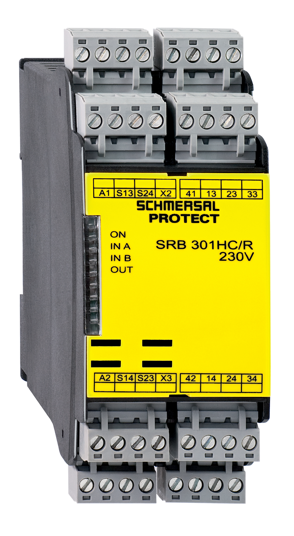
SRB301HC/R-230V
- 3 safety contacts, STOP 0
- 1 Signalling output
- Suitable for the signal processing of outputs with contact sensors
Ordering data
| Replacement article number |
101193477 |
| Product type description |
SRB301HC/R-230V |
| Article number (order number) |
101190596 |
| EAN (European Article Number) |
4250116202324 |
| eCl@ss number, version 12.0 |
27-37-18-19 |
| eCl@ss number, version 11.0 |
27-37-18-19 |
| eCl@ss number, version 9.0 |
27-37-18-19 |
| ETIM number, version 7.0 |
EC001449 |
| ETIM number, version 6.0 |
EC001449 |
| Notice |
Discontinued product |
Approvals - Standards
| Certificates |
TÜV cULus CCC TILVA |
General data
| Standards |
EN IEC 62061 EN ISO 13849-1 EN IEC 60947-5-1 EN IEC 60947-5-3 EN IEC 60947-5-5 EN IEC 61508 EN IEC 60204-1 EN IEC 60947-1 |
| Climatic stress |
EN 60068-2-78 |
| Housing material |
Glass-fibre reinforced thermoplastic, ventilated |
| Gross weight |
300 g |
General data - Features
| Electronic Fuse |
Yes |
| Wire breakage detection |
Yes |
| Cross-circuit detection |
Yes |
| Removable Terminals |
Yes |
| Start input |
Yes |
| Feedback circuit |
Yes |
| Reset edge detection |
Yes |
| Earth connection detection |
Yes |
| Integral system diagnostics, status |
Yes |
| Number of auxiliary contacts |
1 |
| Number of LEDs |
4 |
| Number of normally closed (NC) |
2 |
| Number of safety contacts |
3 |
| Safety classification |
| Standards |
EN IEC 60947-5-1 EN IEC 61508 |
| Stop-Category |
0 |
| Safety classification - Relay outputs |
| Performance Level, stop 0, up to |
e |
| Category, Stop 0 |
4 |
| Diagnostic Coverage (DC) Level, Stop 0 |
≥ 99 % |
| PFH value, Stop 0 |
2.00 x 10⁻⁸ /h |
| Safety Integrity Level (SIL), Stop 0, suitable for applications in |
3 |
| Mission time |
20 Year(s) |
| Common Cause Failure (CCF), minimum |
65 |
Mechanical data
| Mechanical life, minimum |
10,000,000 Operations |
| Mounting |
Snaps onto standard DIN rail to EN 60715 |
Mechanical data - Connection technique
| Terminal designations |
IEC/EN 60947-1 |
| Termination |
rigid or flexible Screw terminals M20 x 1.5 |
| Cable section, minimum |
0.25 mm² |
| Cable section, maximum |
2.5 mm² |
| Tightening torque of Clips |
0.6 Nm |
Mechanical data - Dimensions
| Width |
45 mm |
| Height |
100 mm |
| Depth |
121 mm |
Ambient conditions
| Degree of protection of the enclosure |
IP40 |
| Degree of protection of the mounting space |
IP54 |
| Degree of protection of clips or terminals |
IP20 |
| Ambient temperature |
-25 ... +60 °C |
| Storage and transport temperature |
-40 ... +85 °C |
| Resistance to vibrations |
10 ... 55 Hz, Amplitude 0.35 mm |
| Restistance to shock |
30 g / 11 ms |
Ambient conditions - Insulation values
| Rated impulse withstand voltage Uimp |
4 kV |
| Overvoltage category |
III |
| Degree of pollution |
2 |
Electrical data
| Frequency range |
50 Hz 60 Hz |
| Type of voltage range |
AC |
| Rated operating voltage |
48 ... 240 VAC |
| Rated AC voltage for controls, 50 Hz, minimum |
48 VAC |
| Rated control voltage at AC 50 Hz, maximum |
240 VAC |
| Rated AC voltage for controls, 60 Hz, minimum |
48 VAC |
| Rated control voltage at AC 60 Hz, maximum |
240 VAC |
| Electrical power consumption |
1.6 W |
| Electrical power consumption |
4.2 VA |
| Contact resistance, maximum |
0.1 Ω |
| Note (Contact resistance) |
in new state |
| Drop-out delay in case of power failure, typically |
80 ms |
| Drop-out delay in case of emergency, typically |
20 ms |
| Pull-in delay at automatic start, maximum, typically |
100 ms |
| Pull-in delay at RESET, typically |
20 ms |
| Material of the contacts, electrical |
AgSn0. self-cleaning, positive drive |
Electrical data - Safe relay outputs
| Voltage, Utilisation category AC-15 |
230 VAC |
| Current, Utilisation category AC-15 |
6 A |
| Voltage, Utilisation category DC-13 |
24 VDC |
| Current, Utilisation category DC-13 |
6 A |
| Switching capacity, minimum |
10 VDC |
| Switching capacity, minimum |
10 mA |
| Switching capacity, maximum |
250 VAC |
| Switching capacity, maximum |
8 A |
Electrical data - Digital inputs
| Conduction resistance, maximum |
40 Ω |
Electrical data - Digital Output
| Voltage, Utilisation category DC-12 |
24 VDC |
| Current, Utilisation category DC-12 |
0.1 A |
Electrical data - Relay outputs (auxiliary contacts)
| Switching capacity, maximum |
24 VDC |
| Switching capacity, maximum |
2 A |
Electrical data - Electromagnetic compatibility (EMC)
| EMC rating |
EMC-Directive |
Status indication
| Indicated operating states |
Position relay K2 Position relay K1 |
Other data
| Note (applications) |
Guard system Emergency-Stop button Pull-wire emergency stop switches Two-hand control panels Safety mats |
Note
| Note (General) |
Inductive loads (e.g. contactors, relays, etc.) are to be suppressed by means of a suitable circuit. |
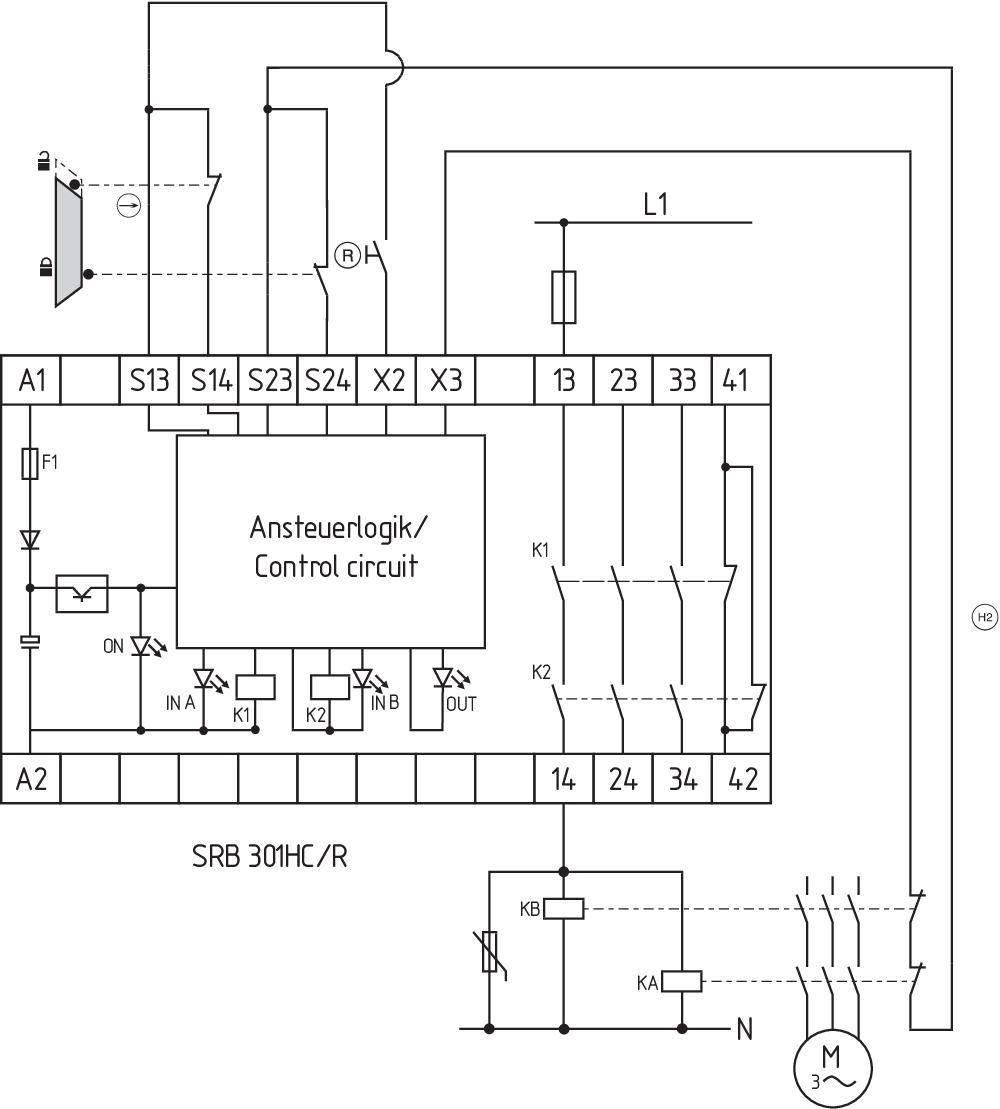
Wiring example
| Note (Wiring diagram) |
The wiring diagram is shown with guard doors closed and in de-energised condition. Relay outputs: Suitable for 2 channel control, for increase in capacity or number of contacts by means of contactors or relays with positive-guided contacts. The control recognises cross-short, cable break and earth leakages in the monitoring circuit. 2 channel control shown for a guard-door monitor with two contacts, of which at least one contact has positive break, with external reset button (R). (H2) = Feedback circuit |
Language filter
Datasheet
Operating instructions and Declaration of conformity
TÜV certification
TILVA-Certificate
UL Certificate
UKCA Declaration of Conformity
Wiring example (electr. wiring)
SISTEMA-VDMA library
Download the latest version of Adobe Reader
Product picture (catalogue individual photo)
Symbol (technical standard)

Wiring example
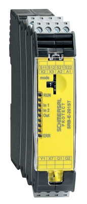
103008067 SRB-E-201ST
- Plug-in screw terminals with coding
- STOP 0 Function
- 1 oder 2-channel control
- Start button / Auto-start
- Monitoring two-hand control panels to EN 574 IIIC
- 2 Safety outputs 5.5 A
- 1 Signalling output

103007672 SRB-E-301ST
- Plug-in screw terminals with coding
- STOP 0 Function
- 1 oder 2-channel control
- Start button / Auto-start
- 1 Auxiliary contact
- 3 safety contacts
| EU-Konformitätserklärung |  |
| Original | K.A. Schmersal GmbH & Co. KG Möddinghofe 30 42279 Wuppertal Germany Internet: www.schmersal.com |
| Erklärung: | Hiermit erklären wir, dass die nachfolgend aufgeführten Bauteile aufgrund der Konzipierung und Bauart den Anforderungen der unten angeführten Europäischen Richtlinien entsprechen. |
| Bezeichnung des Bauteils: | SRB301HC/R-24V SRB301HC/R-230V |
| Beschreibung des Bauteils: | Relais-Sicherheitskombination für NOT-HALT-Schaltungen, Schutztürüberwachungen, Schaltmatten und Zweihand-Überwachung |
| Einschlägige Richtlinien: | Maschinenrichtlinie | 2006/42/EG |
| EMV-Richtlinie | 2014/30/EU | |
| RoHS-Richtlinie | 2011/65/EU |
| Angewandte Normen: | EN 60947-5-1:2017 + AC:2020 EN ISO 13851:2019 EN ISO 13849-1:2015 EN ISO 13849-2:2012 |
| Benannte Stelle der Baumusterprüfung: | TÜV Rheinland Industrie Service GmbH Am Grauen Stein, 51105 Köln Kenn-Nr.: 0035 |
| EG-Baumusterprüfbescheinigung: | 01/205/5157.02/22 |
| Bevollmächtigter für die Zusammenstellung der technischen Unterlagen: | Oliver Wacker Möddinghofe 30 42279 Wuppertal |
| Ort und Datum der Ausstellung: | Wuppertal, 5. Oktober 2022 |
 |
| Rechtsverbindliche Unterschrift Philip Schmersal Geschäftsführer |
Schmersal India Pvt. Ltd., Plot No - G-7/1, Ranjangaon MIDC, Tal. - Shirur, Dist.- Pune 412 220
The details and data referred to have been carefully checked. Images may diverge from original. Further technical data can be found in the manual. Technical amendments and errors possible.
Generated on: 13/05/2024, 6:55 am