BDF200-ST1-AS-NHK-LMRD-LTWH-LTGN
BDF200-ST1-AS-NHK-LMRD-LTWH-LTGN
Descargas
- Integrated AS-Interface
- with connector plug M12 bottom
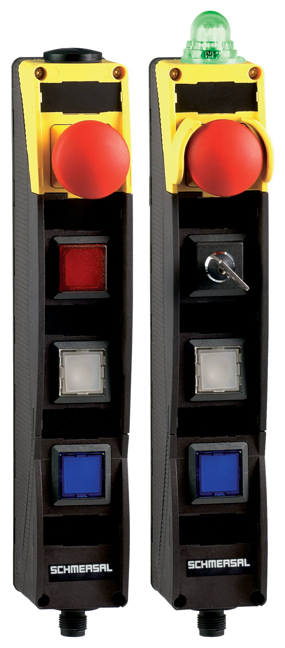
- Pos 1: E-STOP with protective collar
- Pos 2: RED signal light
- Pos 3: WHITE illuminated pushbutton
- Pos 4: GREEN illuminated pushbutton
- slender shock-proof thermoplastic enclosure
- to be installed at an ergonomic favourable position
- to be fitted to commercial-off-the-shelf aluminium profiles
Ordering data
| Product type description |
BDF200-ST1-AS-NHK-LMRD-LTWH-LTGN |
| Article number (order number) |
101215277 |
| EAN (European Article Number) |
4030661448466 |
| eCl@ss number, version 12.0 |
27-37-12-16 |
| eCl@ss number, version 11.0 |
27-37-12-16 |
| eCl@ss number, version 9.0 |
27-37-12-16 |
| ETIM number, version 7.0 |
EC000225 |
| ETIM number, version 6.0 |
EC000225 |
| Note (Ordering data) |
Nota: Ver código de pedidos. |
Approvals - Standards
| Certificates |
cULus ASi-SaW |
General data
| Standards |
EN IEC 62026-2 EN ISO 13849-1 EN ISO 13850 EN IEC 60947-5-1 EN IEC 61508 |
| Climatic stress |
DIN EN 60068 |
| Housing material |
Plástico, termoplástico reforzado con fibra de vidrio, auto-extinguible |
| Reaction time, maximum |
100 ms |
| Positions used, position 1 |
Pulsador de Paro de Emergencia con collar protector |
| Positions used, position 2 |
Piloto luminoso, rojo |
| Positions used, position 3 |
Pulsador luminoso, blanco |
| Positions used, position 4 |
Pulsador luminoso, verde |
| Gross weight |
280 g |
General data - Features
| Indicator lamp |
No |
| Safety classification |
| Vorschriften |
EN IEC 61508 |
| Performance Level, up to |
e |
| Category |
4 |
| PFH value |
1,40 x 10⁻⁸ /h |
| Note (PFH-value) |
hasta un máximo de 5.000 ciclos de conmutación al año |
| Safety Integrity Level (SIL), suitable for applications in |
3 |
| Mission time |
20 Year(s) |
Mechanical data
| Mechanical life, Emergency-Stop button |
100.000 Operations |
| Mechanical life, Command devices |
1.000.000 Operations |
| Mounting |
orificios de montaje interiores |
| Type of the fixing screws |
2x M5 |
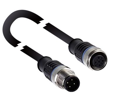
Mechanical data - Connection technique
| Termination |
Conector empotrado M12, 4-polos, codificación A |
Mechanical data - Dimensions
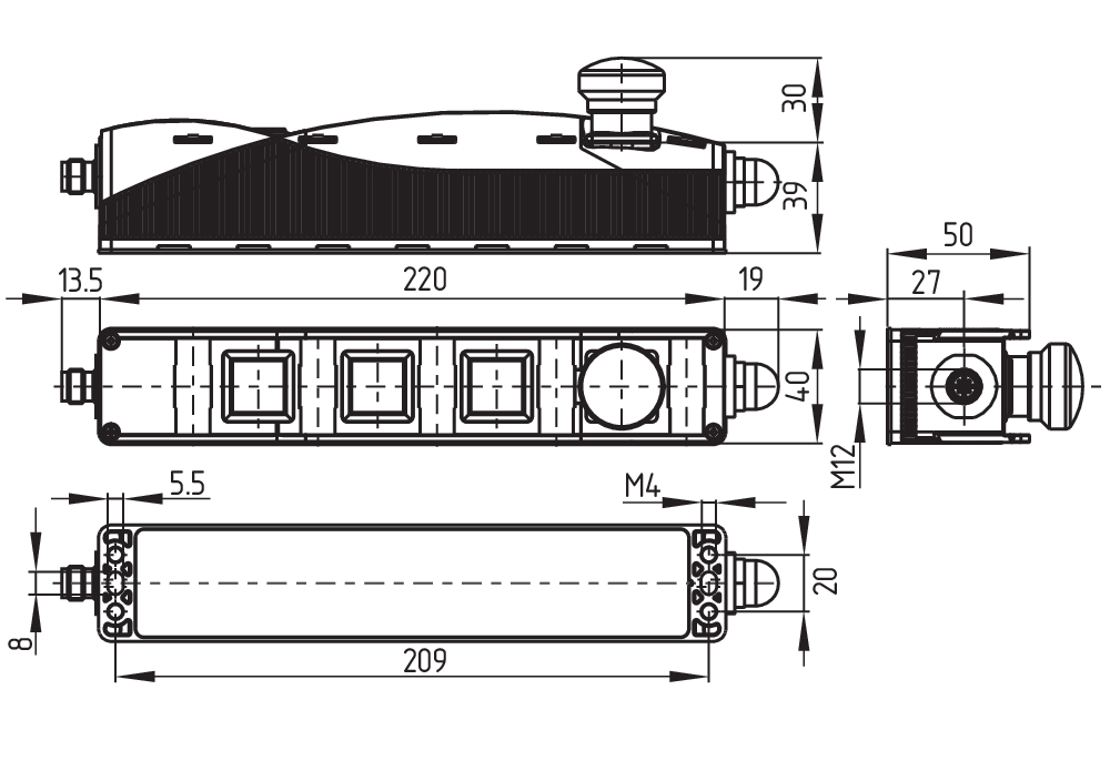
| Width |
40 mm |
| Height |
69 mm |
| Depth |
233,5 mm |
Ambient conditions
| Degree of protection |
IP65 |
| Ambient temperature |
-25 ... +65 °C |
| Storage and transport temperature |
-25 ... +85 °C |
| Resistance to vibrations |
10 … 150 Hz, amplitud 0,35 mm / 5 g |
| Restistance to shock |
15 g / 11 ms |
| Protection class |
II |
| Permissible installation altitude above sea level, maximum |
2.000 m |
Ambient conditions - Insulation values
| Rated insulation voltage Ui |
32 VDC |
| Rated impulse withstand voltage Uimp |
0,8 kV |
| Overvoltage category |
III |
| Degree of pollution |
3 |
Electrical data - AS Interface
| Rated operating voltage |
18 ... 31,6 VDC (Protection against polarity reversal) |
| AS-i Current consumption, maximum |
150 mA |
Electrical data - AS-Interface specification
| Note (AS-i Parameter bits) |
Las salidas de parámetro deben configurarse en "1111" (0xF). FID: error periférico. |
| AS-i Version (Safety-Slave) |
V 3.0 |
| AS-i Profile (Safety-Slave) |
S-7.B.F.F |
| AS-i Input, Channel 1 (Safety-Slave) |
Bits de datos DI 0/DI 1 = transmisón dinámica de códigos |
| AS-i Input, Channel 2 (Safety-Slave) |
Bits de datos DI 2/DI 3 = transmisón dinámica de códigos |
| AS-i Output, DO 0 (Safety-Slave) |
Lámpara piloto G24 rojo |
| AS-i Output, DO 1 (Safety-Slave) |
Lámpara piloto G24 verde |
| AS-i Output, DO 2 (Safety-Slave) |
Sin función |
| AS-i Output, DO 3 (Safety-Slave) |
Sin función |
| AS-i AS-i Parameter bits (Safety-Slave), P0 ... P3 |
Sin función |
| AS-i Version (A/B Slave) |
V 3.0 |
| AS-i Profile (A/B Slave) |
S-7.A.7.F |
| AS-i Input, DI 0 (A/B Slave) |
Dispositivo de mando Posición 4 |
| AS-i Input, DI 1 (A/B Slave) |
Dispositivo de mando Posición 3 |
| AS-i Input, DI 2 (A/B Slave) |
Dispositivo de mando Posición 2 |
| AS-i Input, DI 3 (A/B Slave) |
Dispositivo de mando Posición 2 |
| AS-i Output, DO 0 (A/B Slave) |
Piloto luminoso Posición 4 |
| AS-i Output, DO 2 (A/B Slave) |
Piloto luminoso Posición 2 |
| AS-i Output, DO 1 (A/B Slave) |
Piloto luminoso Posición 3 |
| AS-i Output, DO 3 (A/B Slave) |
Sin función |
| AS-i AS-i Parameter bits (A/B Slave), P0 ... P3 |
Sin función |
| AS-i Input module address |
0 |
| Note (AS-i Input module address) |
Predeterminado en dirección 0, posibilidad de modificación a través de maestro de bus AS-Interface o dispositivo de programación manual |
| Note |
Ambos esclavos AS-i pueden ser habilitados y deshabilitados con el interruptor DIP integrado. El direccionamiento debe ser hecho con el conector M12 |
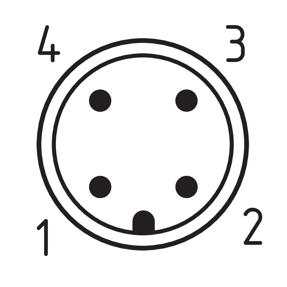
Pin assignment
| PIN 1 |
AS-Interface + |
| PIN 2 |
n.c. |
| PIN 3 |
AS-Interface - |
| PIN 4 |
n.c. |
Filtro de idiomas
Ficha técnica
Manual de instrucciones y declaración de conformidad
Certificado UL
Certificado Interfaz AS at Work
Descargar la versión actual de Adobe Reader
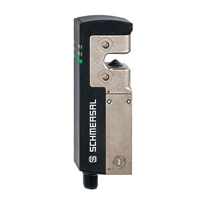
Foto de producto (foto individual de catálogo)
Dibujo dimensional Componente básico
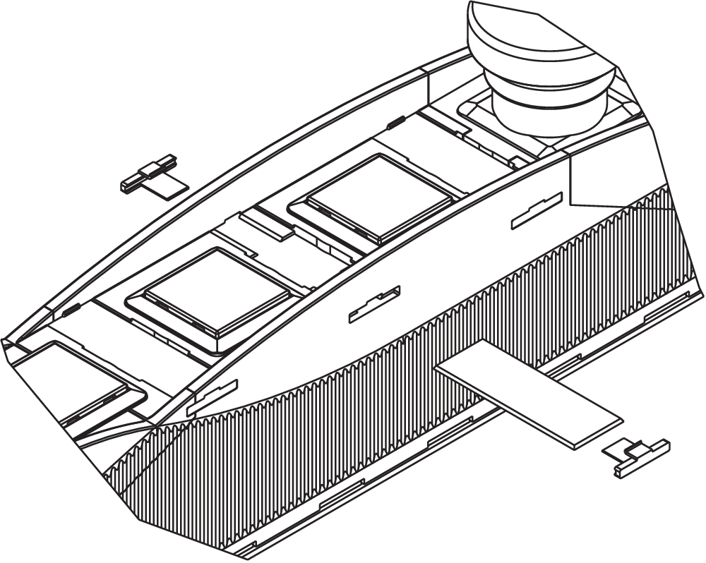
Principio de funcionamiento
Clipart

Esquema de contactos
| EU Declaration of Conformity |  |
| Original | K.A. Schmersal GmbH & Co. KG Möddinghofe 30 42279 Wuppertal Germany Internet: www.schmersal.com |
| Declaration: | We hereby certify that the hereafter described components both in their basic design and construction conform to the applicable European Directives. |
| Name of the component: | BDF200AS |
| Type: | See ordering code |
| Description of the component: | Control panel with or without safety function and integrated AS interface |
| Relevant Directives: | Machinery Directive 1) | 2006/42/EC |
| Low Voltage Directive | 2014/35/EU | |
| EMC-Directive | 2014/30/EU | |
| RoHS-Directive | 2011/65/EU | |
| 1) For device versions with safety function | ||
| Applied standards: | EN 60947-5-1:2017 + AC:2020 1) EN 60947-5-5:1997 + A1:2005 + A11:2013 + A2:2017 1) EN ISO 13849-1:2023 1) EN 61508-1:2010 |
| Person authorised for the compilation of the technical documentation: | Oliver Wacker Möddinghofe 30 42279 Wuppertal |
| Place and date of issue: | Wuppertal, December 10, 2024 |
 |
| Authorised signature Philip Schmersal Managing Director |
Schmersal India Pvt. Ltd., Plot No - G-7/1, Ranjangaon MIDC, Tal. - Shirur, Dist.- Pune 412 220
Los datos e información anteriores se han verificado cuidadosamente. Las imágenes pueden diferir del original. Se pueden encontrar más datos técnicos en los manuales de instrucciones. Sujeto a cambios técnicos y errores.
Generado a 16/4/2025 5:34
Historial
AZM40B-ST-1P2P-PH