SRB301LC/B 24V

SRB301LC/B 24V
- Suitable for the signal processing of outputs with contact sensors
- Suitable for the signal processing of outputs with contact sensors
- Suitable for signal processing of outputs connected to potentials (AOPDs), e.g. safety light grids/curtains
- 3 safety contacts, STOP 0
- 1 Signalling output
Ordering data
| Product type description |
SRB301LC/B 24V |
| Article number (order number) |
101177962 |
| EAN (European Article Number) |
4250116201686 |
| eCl@ss number, version 12.0 |
27-37-18-19 |
| eCl@ss number, version 11.0 |
27-37-18-19 |
| eCl@ss number, version 9.0 |
27-37-18-19 |
| ETIM number, version 7.0 |
EC001449 |
| ETIM number, version 6.0 |
EC001449 |
| Notice |
Auslaufprodukt |
Approvals - Standards
| Certificates |
cULus CCC |
General data
| Standards |
EN IEC 62061 EN ISO 13849-1 EN IEC 60947-5-1 EN IEC 60947-5-3 EN IEC 60947-5-5 EN IEC 61508 EN IEC 60204-1 EN IEC 60947-1 |
| Climatic stress |
EN 60068-2-78 |
| Housing material |
Kunststoff, glasfaserverstärkter Thermoplast, belüftet |
| Gross weight |
230 g |
General data - Features
| Wire breakage detection |
Ja |
| Start input |
Ja |
| Feedback circuit |
Ja |
| Automatic reset function |
Ja |
| Earth connection detection |
Ja |
| Integral system diagnostics, status |
Ja |
| Number of auxiliary contacts |
1 |
| Number of LEDs |
4 |
| Number of normally closed (NC) |
2 |
| Number of safety contacts |
3 |
| Safety classification |
| Vorschriften |
EN IEC 60947-5-1 EN IEC 61508 |
| Stop-Category |
0 |
| Safety classification - Relay outputs |
| Performance Level, stop 0, up to |
e |
| Category, Stop 0 |
4 |
| Diagnostic Coverage (DC) Level, Stop 0 |
≥ 99 % |
| PFH value, Stop 0 |
2,00 x 10⁻⁸ /h |
| Safety Integrity Level (SIL), Stop 0, suitable for applications in |
3 |
| Mission time |
20 Year(s) |
| Common Cause Failure (CCF), minimum |
65 |
Mechanical data
| Mechanical life, minimum |
10.000.000 Operations |
| Mounting |
Schnellbefestigung für Normschiene nach DIN EN 60715 |
Mechanical data - Connection technique
| Terminal designations |
IEC/EN 60947-1 |
| Termination |
starr oder flexibel Schraubanschluss M20 x 1.5 |
| Cable section, minimum |
0,25 mm² |
| Cable section, maximum |
2,5 mm² |
| Tightening torque of Clips |
0,6 Nm |
Mechanical data - Dimensions
| Width |
22,5 mm |
| Height |
100 mm |
| Depth |
121 mm |
Ambient conditions
| Degree of protection of the enclosure |
IP40 |
| Degree of protection of the mounting space |
IP54 |
| Degree of protection of clips or terminals |
IP20 |
| Ambient temperature |
-25 ... +45 °C |
| Storage and transport temperature |
-40 ... +85 °C |
| Resistance to vibrations |
10 ... 55 Hz, Amplitude 0,35 mm, ± 15 % |
| Restistance to shock |
30 g / 11 ms |
Ambient conditions - Insulation values
| Rated impulse withstand voltage Uimp |
4 kV |
| Overvoltage category |
III |
| Degree of pollution |
2 |
Electrical data
| Frequency range |
50 Hz 60 Hz |
| Operating voltage |
24 VAC -15 % / +10 % |
| Ripple voltage |
10 % |
| Rated operating voltage |
24 VAC |
| Rated operating voltage |
24 VDC |
| Rated AC voltage for controls, 50 Hz, minimum |
20,4 VAC |
| Rated control voltage at AC 50 Hz, maximum |
26,4 VAC |
| Rated AC voltage for controls, 60 Hz, minimum |
20,4 VAC |
| Rated control voltage at AC 60 Hz, maximum |
26,4 VAC |
| Rated AC voltage for controls at DC minimum |
20,4 VDC |
| Rated control voltage at DC, maximum |
28,8 VDC |
| Electrical power consumption |
1,7 W |
| Electrical power consumption |
1,9 VA |
| Contact resistance, maximum |
0,1 Ω |
| Note (Contact resistance) |
in Neuzustand |
| Drop-out delay in case of power failure, typically |
80 ms |
| Drop-out delay in case of emergency, typically |
20 ms |
| Pull-in delay at automatic start, maximum, typically |
100 ms |
| Pull-in delay at RESET, typically |
20 ms |
| Material of the contacts, electrical |
AgSnO, selbstreinigend, zwangsgeführt |
Electrical data - Safe relay outputs
| Voltage, Utilisation category AC-15 |
230 VAC |
| Current, Utilisation category AC-15 |
6 A |
| Voltage, Utilisation category DC-13 |
24 VDC |
| Current, Utilisation category DC-13 |
6 A |
| Switching capacity, minimum |
10 VDC |
| Switching capacity, minimum |
10 mA |
| Switching capacity, maximum |
250 VAC |
| Switching capacity, maximum |
8 A |
Electrical data - Digital inputs
| Conduction resistance, maximum |
40 Ω |
Electrical data - Digital Output
| Voltage, Utilisation category DC-12 |
24 VDC |
| Current, Utilisation category DC-12 |
0,1 A |
Electrical data - Relay outputs (auxiliary contacts)
| Switching capacity, maximum |
24 VDC |
| Switching capacity, maximum |
2 A |
Electrical data - Electromagnetic compatibility (EMC)
| EMC rating |
EMV-Richtlinie |
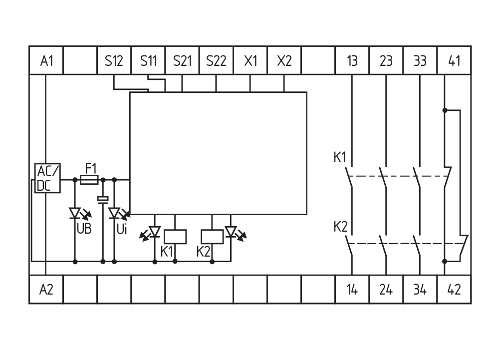
Status indication
| Indicated operating states |
Stellung der Relais K2 Stellung der Relais K1 Interne Betriebsspannung Ui |
Other data
| Note (applications) |
Sicherheits-Sensor Schutzeinrichtung NOT-HALT-Taster Seilzug-Notschalter Sicherheits-Lichtvorhang |
Note
| Note (General) |
Induktive Verbraucher (Schütze, Relais etc.) sind durch eine geeignete Beschaltung zu entstören. |
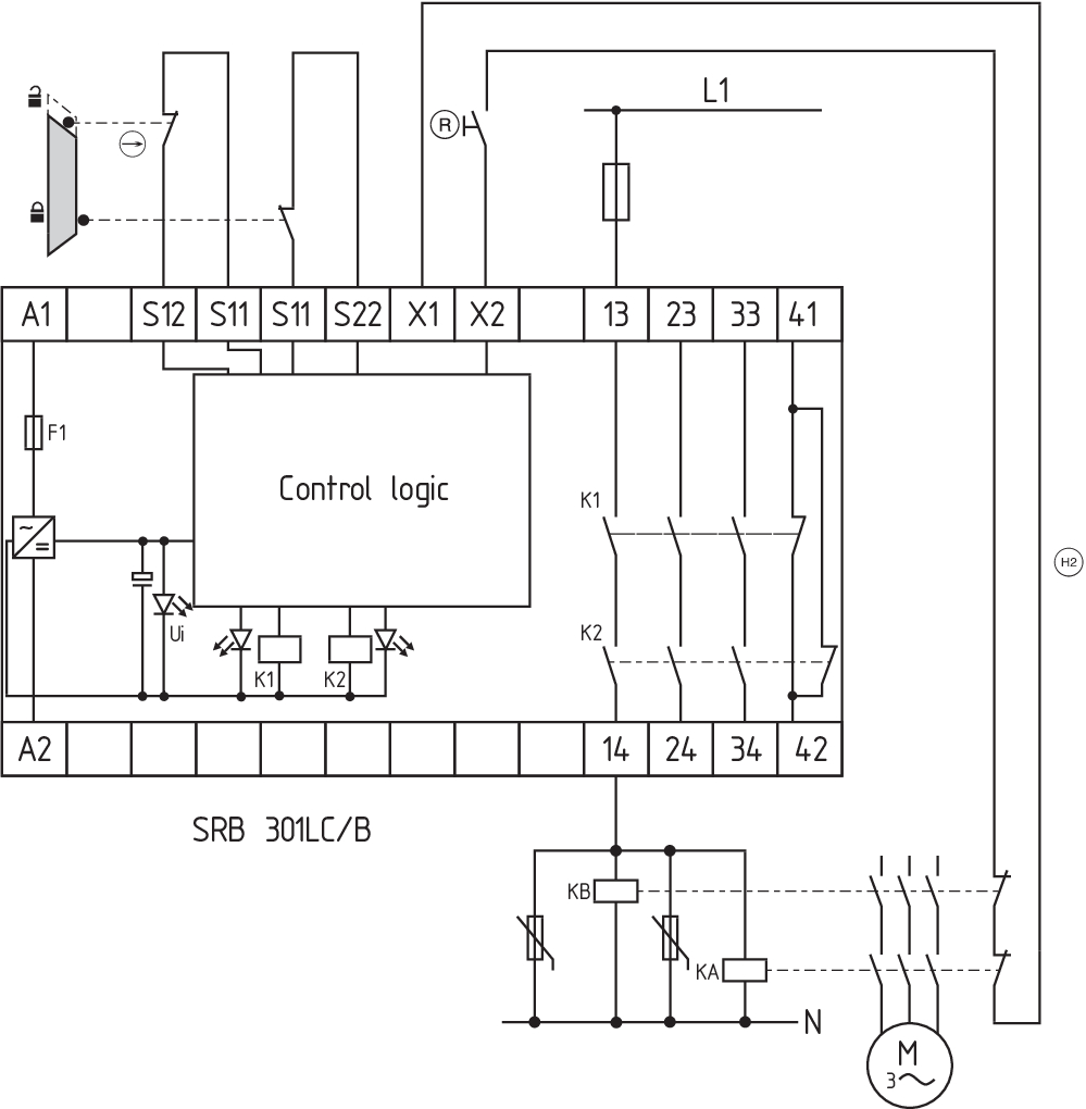
Wiring example
| Note (Wiring diagram) |
Das Schaltungsbeispiel ist bei geschlossenen Schutzeinrichtungen und im spannungslosen Zustand dargestellt. Die Ansteuerung erkennt Drahtbrüche und Erdschlüsse im Überwachungskreis. Leistungsebene: 2-kanalige Ansteuerung geeignet zur Kontaktverstärkung bzw. Kontaktvervielfältigung durch Schütze oder Relais mit zwangsgeführten Kontakten. Automatischer Start: Die Programmierung auf automatischen Start erfolgt durch die Einbindung des Rückführkreises an die Klemmen X1/X2. Bei nicht benötigtem Rückführkreis ist dieser durch eine Brücke zu ersetzen. Bei 1-kanaliger Ansteuerung den Öffnerkontakt S11/S12 anschließen und S12/S22 brücken Potenzialbehaftete Ausgänge von Lichtgittern/-vorhängen (p-schaltend) an S12/S22 anschließen. Die Geräte müssen auf gleichem Bezugspotenzial liegen. Eingangsebene: 2-kanalige Ansteuerung, dargestellt am Beispiel einer Schutztürüberwachung mit zwei Positionsschaltern, davon einer zwangsöffnend, externem Reset-Taster (R); Querschlusserkennung und Rückführkreis (H2) |
Sprachfilter
Datenblatt
Betriebsanleitung und Konformitätserklärung
UL-Zertifikat
CCC-Zertifikat
Schaltungsbeispiel (elektr. Verdrahtung)
SISTEMA-VDMA Bibliothek/Library
Download der aktuellen Version von Adobe Reader
Produktbild (Katalogeinzelphoto )
Schaltungsbeispiel
Schaltungsbeispiel
Schaltungsbeispiel

Symbol (technischer Standard)

103014374 SRB-E-301MC
- 1 Signalling contact
- Plug-in screw terminals with coding
- Suitable for applications up to Cat. 4 / PL e und up to SIL 3
- 1 or 2 channel signal evaluation
- Start / feedback circuit monitoring
- Optionally with short-circuit recognition
- 3 safety contacts, stop category 0
| EU-Konformitätserklärung |  |
| Original | K.A. Schmersal GmbH & Co. KG Möddinghofe 30 42279 Wuppertal Germany Internet: www.schmersal.com |
| Erklärung: | Hiermit erklären wir, dass die nachfolgend aufgeführten Bauteile aufgrund der Konzipierung und Bauart den Anforderungen der unten angeführten Europäischen Richtlinien entsprechen. |
| Bezeichnung des Bauteils: | SRB301LC/B SRB301LC/B-R |
| Beschreibung des Bauteils: | Relais-Sicherheitskombination für NOT-HALT-Schaltungen und Schutztürüberwachungen |
| Einschlägige Richtlinien: | Maschinenrichtlinie | 2006/42/EG |
| EMV-Richtlinie | 2014/30/EU | |
| RoHS-Richtlinie | 2011/65/EU |
| Angewandte Normen: | EN 60947-5-1:2004 + AC:2005 + A1:2009 EN 60947-5-1:2017 EN ISO 13849-1:2015 EN ISO 13849-2:2012 EN ISO 13850:2015 EN 61326-3-1:2017 |
| Benannte Stelle für die Zertifizierung des QS-Systems nach Anhang X, 2006/42/EG: | TÜV Rheinland Industrie Service GmbH Am Grauen Stein, 51105 Köln Kenn-Nr.: 0035 |
| Bevollmächtigter für die Zusammenstellung der technischen Unterlagen: | Oliver Wacker Möddinghofe 30 42279 Wuppertal |
| Ort und Datum der Ausstellung: | Wuppertal, 22. November 2021 |
 |
| Rechtsverbindliche Unterschrift Philip Schmersal Geschäftsführer |
Schmersal India Pvt. Ltd., Plot No - G-7/1, Ranjangaon MIDC, Tal. - Shirur, Dist.- Pune 412 220
Die genannten Daten und Angaben wurden sorgfältig geprüft. Abbildungen können vom Original abweichen. Weitere technische Daten finden Sie in der Betriebsanleitung. Technische Änderungen und Irrtümer vorbehalten.
Generiert am: 11.03.2025, 17:21