FWS 2105 A UE: 24...230V AC/DC
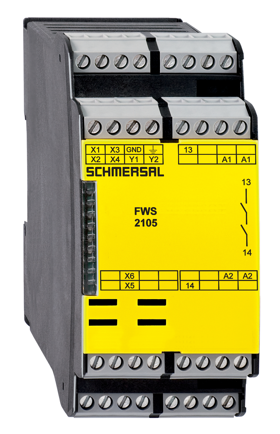
FWS 2105 A UE: 24...230V AC/DC
- Detects standstill using 2 impulse sensor(s)
- 1 safety contact
- 2 Signalling outputs
Ordering data
| Note (Delivery capacity) |
Not available! |
| Product type description |
FWS 2105 A UE: 24...230V AC/DC |
| Article number (order number) |
101181691 |
| EAN (European Article Number) |
4030661323213 |
| eCl@ss number, version 12.0 |
27-37-18-19 |
| eCl@ss number, version 11.0 |
27-37-18-19 |
| eCl@ss number, version 9.0 |
27-37-18-19 |
| ETIM number, version 7.0 |
EC001449 |
| ETIM number, version 6.0 |
EC001449 |
| Available until |
31.12.2024 |
Approvals - Standards
| Certificates |
cULus |
General data
| Standards |
BG-GS-ET-20 EN IEC 62061 EN ISO 13849-1 EN IEC 60947-5-1 EN IEC 60947-5-3 EN IEC 60947-5-5 EN IEC 60204-1 EN IEC 60947-1 |
| Climatic stress |
EN 60068-2-3 BG-GS-ET-14 |
| Housing material |
Glass-fibre reinforced thermoplastic, ventilated |
| Gross weight |
283 g |
General data - Features
| Wire breakage detection |
Yes |
| Automatic reset function |
Yes |
| Reset after disconnection of supply voltage |
Yes |
| Integral system diagnostics, status |
Yes |
| Number of LEDs |
1 |
| Number of undelayed semi-conductor outputs with signaling function |
2 |
| Number of safety contacts |
1 |
| Number of signalling outputs |
2 |
| Safety classification |
| Standards |
EN IEC 61508 |
| Performance Level, up to |
d |
| Category |
3 |
| PFH value |
1.00 x 10⁻⁷ /h |
| Safety Integrity Level (SIL), suitable for applications in |
2 |
| Mission time |
20 Year(s) |
| Stop-Category |
0 |
Mechanical data
| Mechanical lifetime, minimum |
20,000,000 Operations |
| Mounting |
Snaps onto standard DIN rail to EN 60715 |
Mechanical data - Connection technique
| Terminal designations |
IEC/EN 60947-1 |
| Termination |
rigid or flexible Screw terminals M20 x 1.5 |
| Cable section, minimum |
0.2 mm² |
| Cable section, maximum |
2.5 mm² |
| Tightening torque of Clips |
0.6 Nm |
Mechanical data - Dimensions
| Width |
45 mm |
| Height |
100 mm |
| Depth |
121 mm |
Ambient conditions
| Degree of protection of the enclosure |
IP40 |
| Degree of protection of the installation space |
IP54 |
| Degree of protection of clips or terminals |
IP20 |
| Ambient temperature |
+0 ... +55 °C |
| Storage and transport temperature |
-25 ... +70 °C |
| Resistance to vibrations |
10 ... 55 Hz, Amplitude 0.35 mm |
| Restistance to shock |
30 g / 11 ms |
Ambient conditions - Insulation values
| Rated impulse withstand voltage Uimp |
4.8 kV |
| Overvoltage category |
III |
| Degree of pollution |
2 |
Electrical data
| Type of voltage range |
AC DC |
| Rated operating voltage |
24 ... 230 VAC |
| Rated AC voltage for controls, 50 Hz, minimum |
20.4 VAC |
| Rated control voltage at AC 50 Hz, maximum |
253 VAC |
| Rated AC voltage for controls, 60 Hz, minimum |
20.4 VAC |
| Rated control voltage at AC 60 Hz, maximum |
253 VAC |
| Rated AC voltage for controls at DC minimum |
20.4 VDC |
| Rated control voltage at DC, maximum |
253 VDC |
| Electrical power consumption, maximum |
5 W |
| Contact resistance, maximum |
0.1 Ω |
| Note (Contact resistance) |
in new state |
| Material of the contacts, electrical |
Ag-Ni + Au |
Electrical data - Safe relay outputs
| Voltage, Utilisation category AC-15 |
230 VAC |
| Current, Utilisation category AC-15 |
3 A |
| Voltage, Utilisation category DC-13 |
24 VDC |
| Current, Utilisation category DC-13 |
2 A |
| Switching capacity, minimum |
10 VDC |
| Switching capacity, minimum |
10 mA |
| Switching capacity, maximum |
250 VAC |
| Switching capacity, maximum |
6 A |
Electrical data - Digital inputs
| Input signal, HIGH Signal "1" |
10 … 30 VDC |
| Input signal, LOW Signal "0" |
0 … 2 VDC |
| Conduction resistance, maximum |
40 Ω |
Integral system diagnosis (ISD)
| Note (ISD -Faults) |
The following faults are registered by the safety monitoring modules and indicated by ISD. |
| Faults |
Failure of the safety relay to pull-in or drop-out Fault on the input circuits or the relay control circuits of the safety monitoring module Failure of the proximity switches Failure of one channel being evaluated Interruption of the connections to the inductive proximity switches |
Other data
| Note (applications) |
safe standstill monitoring |
Note
| Note (General) |
Inductive loads (e.g. contactors, relays, etc.) are to be suppressed by means of a suitable circuit. |
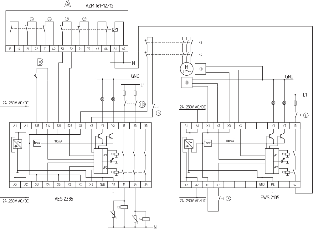
Wiring example
| Note (Wiring diagram) |
The wiring diagram is shown with guard doors closed and in de-energised condition. The ISD tables (Intergral System Diagnostics) for analysis of the fault indications and their causes are shown in the appendix. To monitor one guard door at plants with dangerous run-on movements up to PL d and Category 3 Standstill monitoring for unlocking solenoid interlocks The solenoid interlock can be opened, when the fail-safe standstill monitor has detected the end of the run-on movement by means of two inductive proximity switches. When the button (E) is actuated, the coil of the solenoid interlock is energised. For suitable IFL range p-type inductive proximity switches, refer to "Schmersal Catalogue Automatisierungstechnik". |
Language filter
Datasheet
Operating instructions and Declaration of conformity
UL Certificate
Info
Wiring example (electr. wiring)
SISTEMA-VDMA library
Download the latest version of Adobe Reader
Product picture (catalogue individual photo)
Wiring example
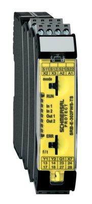
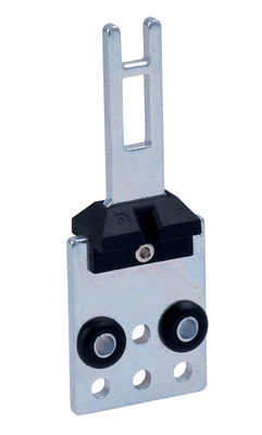
103014754 SRB-E-302FWS-TS
- 2 Safety contacts, 1 Safety Output
- Plug-in screw terminals with coding
- 1 Signalling output - status safety module
- 1 Signalling output - failure massage dynamic
- Detects standstill using 1 or 2 impulse sensors
- additional standstill signal, e.g. PLC as second input channel
- 2-channel time monitoring
| EU Declaration of Conformity |  |
| Original | K.A. Schmersal GmbH & Co. KG Möddinghofe 30 42279 Wuppertal Germany Internet: www.schmersal.com |
| Declaration: | We hereby certify that the hereafter described components both in their basic design and construction conform to the applicable European Directives. |
| Name of the component: | FWS 2105 |
| Type: | See ordering code |
| Description of the component: | Fail-safe standstill monitor |
| Relevant Directives: | Machinery Directive | 2006/42/EC |
| EMC-Directive | 2014/30/EU | |
| RoHS-Directive | 2011/65/EU |
| Applied standards: | EN 60947-5-1:2017 + AC:2020 EN ISO 13849-1: 2015 EN ISO 13849-2: 2012 |
| Notified body, which approved the full quality assurance system, referred to in Appendix X, 2006/42/EC: | TÜV Rheinland Industrie Service GmbH Am Grauen Stein, 51105 Köln ID n°: 0035 |
| Person authorised for the compilation of the technical documentation: | Oliver Wacker Möddinghofe 30 42279 Wuppertal |
| Place and date of issue: | Wuppertal, August 4, 2023 |
 |
| Authorised signature Philip Schmersal Managing Director |
Schmersal Ltd., Sparrowhawk Close, WR14 1GL Malvern
The details and data referred to have been carefully checked. Images may diverge from original. Further technical data can be found in the manual. Technical amendments and errors possible.
Generated on: 19/10/2025, 08:33
Recently viewed
SHGV/R01/220+BO
PS216-Z11-R200-U2