AZ 16-12ZI-B6R-M20
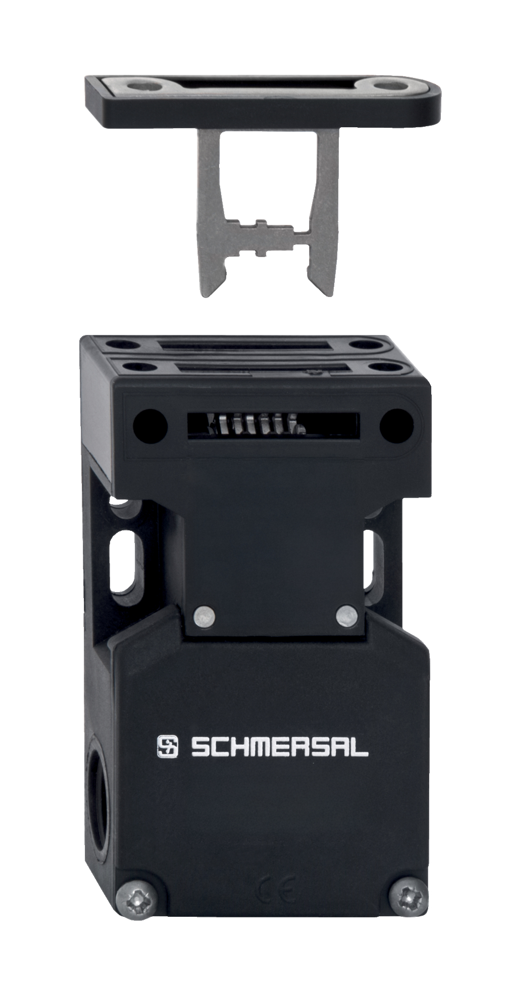
AZ 16-12ZI-B6R-M20
| Product type description: AZ 16-(1)ZI-(2)-(3) |
| (1) | |
| 03 | 3 NC contact |
| 12 | 1 NO contact/2 NC contacts |
| (2) | |
| B1 | straight design |
| B1-1747 | straight design with magnetic latch |
| B1-2024 | straight design with slot-lip seal |
| B1-2053 | straight design with ball latch |
| B1-2177 | straight design with centering guide |
| B6L | angled, flexible to the left |
| B6R | angled, flexible to the right |
| (3) | |
| M16 | cable entry M16 |
| M20 | Cable entry M20 |
- 3 cable entries M 16 x 1.5
- Thermoplastic enclosure
- Individual coding
- Coding level "High" according to ISO 14119
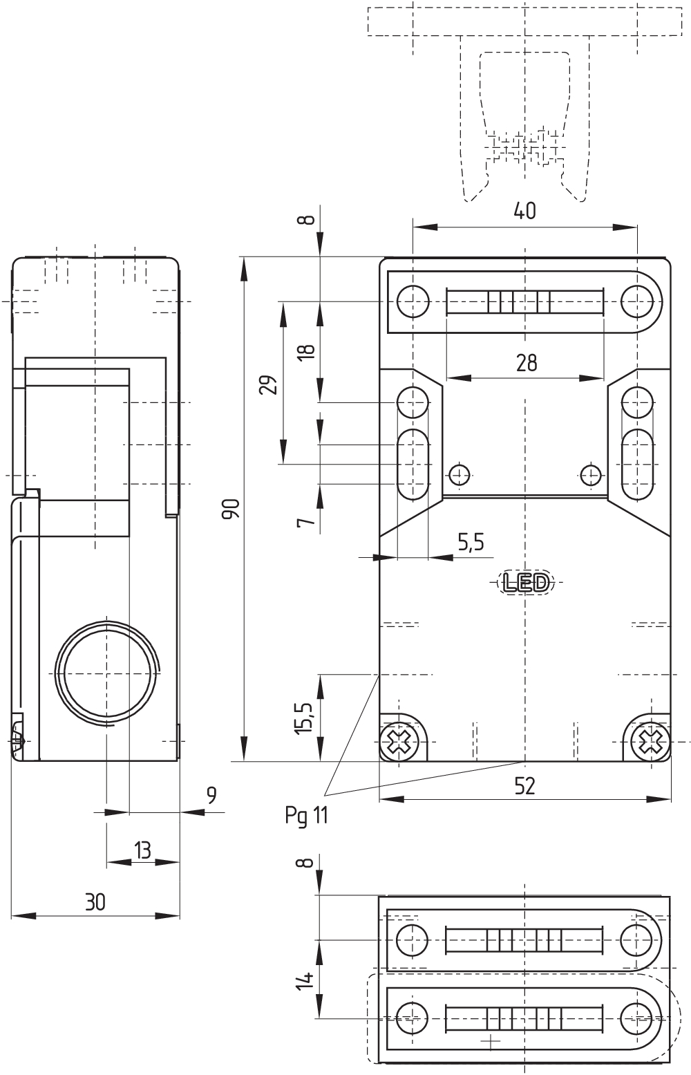
- 52 mm x 90 mm x 30 mm
- Long life
- Double-insulated
- Large wiring compartment
- High level of contact reliability with low voltages and currents
- Insensitive to soiling
- Slotted holes for adjustment, circular holes for location
Ordering data
| Product type description |
AZ 16-12ZI-B6R-M20 |
| Article number (order number) |
103010579 |
| EAN (European Article Number) |
4030661473109 |
| eCl@ss number, version 12.0 |
27-27-26-02 |
| eCl@ss number, version 11.0 |
27-27-26-02 |
| eCl@ss number, version 9.0 |
27-27-26-02 |
| ETIM number, version 7.0 |
EC002592 |
| ETIM number, version 6.0 |
EC002592 |
Approvals - Standards
| Certificates |
cULus |
General data
| Standards |
EN ISO 13849-1 EN ISO 14119 EN IEC 60947-5-1 |
| Coding level according to EN ISO 14119 |
High |
| Housing material |
Plastic, glass-fibre reinforced thermoplastic, self-extinguishing |
| Material of the actuator |
Stainless steel |
| Gross weight |
200 g |
General data - Features
| Ejection force |
Yes |
| Number of auxiliary contacts |
1 |
| Number of safety contacts |
2 |
| Safety classification |
| Vorschriften |
EN ISO 13849-1 |
| Performance Level, up to |
c |
| Category |
1 |
| B10D Normally-closed contact (NC) |
2,000,000 Operations |
| Note |
Electrical life on request. |
| B10D Normally-open contact (NO) |
1,000,000 Operations |
| Note |
at 10% Ie and ohmic load |
| Mission time |
20 Year(s) |
| Safety classification - Fault exclusion |
| Please note: |
Can be used when fault exclusion for dangerous damage to the 1-channel mechanism is permissible and sufficient protection against manipulation is guaranteed. |
| Performance Level, up to |
d |
| Category |
3 |
| Note |
for 2-channel use and with suitable logic unit. |
| Mission time |
20 Year(s) |
Mechanical data
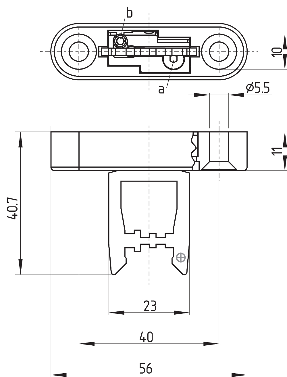
| Actuating radius, minimum |
35 mm |
| Actuator |
angled flexible |
| Mechanical life, minimum |
1,000,000 Operations |
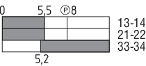
| Positive break travel |
8 mm |
| Positive break force per NC contact, minimum |
10 N |
| Actuating speed, maximum |
2 m/s |
| Mounting |
Screws |
| Type of the fixing screws |
2x M6 |
Mechanical data - Connection technique
| Cable entry |
3 x M20 x 1,5 |
| Termination |
Screw terminals |
| Cable section, minimum |
0.75 mm² |
| Cable section, maximum |
2.5 mm² |
| Note |
All indications including the conductor ferrules. |
Mechanical data - Dimensions
| Length of sensor |
30 mm |
| Width of sensor |
52 mm |
| Height of sensor |
90 mm |
Ambient conditions
| Degree of protection |
IP67 |
| Ambient temperature |
-30 ... +80 °C |
| Storage and transport temperature |
-40 ... +85 °C |
| Permissible installation altitude above sea level, maximum |
2,000 m |
Ambient conditions - Insulation values
| Rated insulation voltage Ui |
500 V |
| Rated impulse withstand voltage Uimp |
6 kV |
| Overvoltage category |
III |
| Degree of pollution |
3 |
Electrical data
| Thermal test current |
10 A |
| Required rated short-circuit current |
1,000 A |
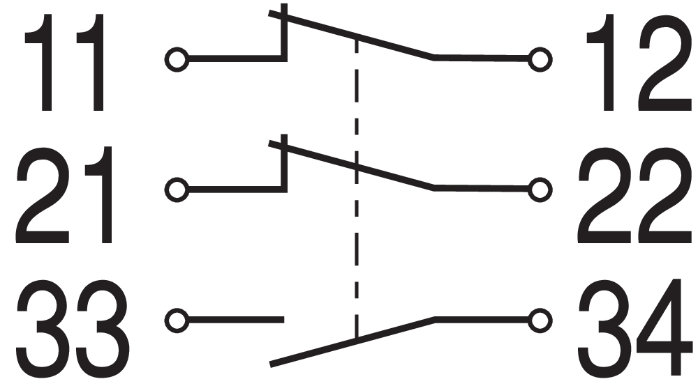
| Switching element |
1 NO contact, 2 NC contacts |
| Switching principle |
slow action, positive break NC contact |
| Maximale Schalthäufigkeit |
4,000 /h |
| Material of the contacts, electrical |
Silver |
Electrical data - Safety contacts
| Voltage, Utilisation category AC-15 |
230 VAC |
| Current, Utilisation category AC-15 |
4 A |
| Voltage, Utilisation category DC-13 |
24 VDC |
| Current, Utilisation category DC-13 |
4 A |
Electrical data - Auxiliary contacts
| Voltage, Utilisation category AC-15 |
230 VAC |
| Current, Utilisation category AC-15 |
4 A |
| Voltage, Utilisation category DC-13 |
24 VDC |
| Current, Utilisation category DC-13 |
4 A |
Scope of delivery
| Scope of delivery |
Individually coded actuator B6 right-hand model |
Note
| Note (General) |
The axis of the hinge must be 5 mm above and in a parallel plane to the top surface of the safety switch. Minimum actuating radius on hinged guards 35 mm The actuator is not available separately. |
Language filter
Datasheet
Operating instructions and Declaration of conformity
UL Certificate
SISTEMA-VDMA library
Download the latest version of Adobe Reader
Product picture (catalogue individual photo)
Dimensional drawing basic component
Dimensional drawing actuator
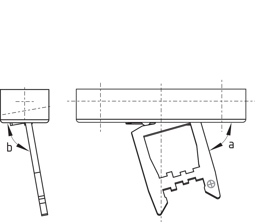
Dimensional drawing actuator
Switch travel diagram
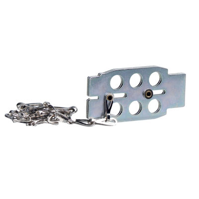
101110500 LOCKOUT TAG SZ 16/335
- To prevent inadvertent closing, e.g. during maintenance
- For complex plant
- Prevents actuation of the switch
- Up to 6 padlocks can be fitted
- The lockout tag can be mounted on a chain near to the safety switch
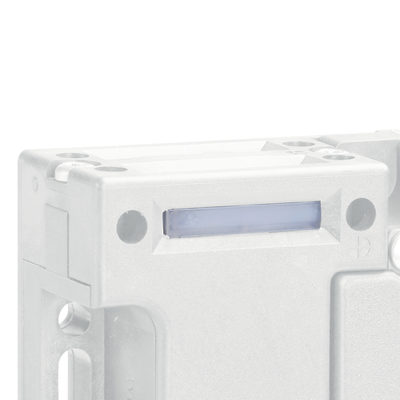
101089116 Slot sealing plug AZ 15/16-1476
- For protection against the ingress of course dirt
- To cover unused actuator slots
- Simple clip-in fitting

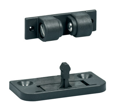
101115025 SET BC 2053-2
- Additional ball latch for stable latching of light to medium-weight guards
- For separate mounting on the guard
Schmersal India Pvt. Ltd., Plot No - G-7/1, Ranjangaon MIDC, Tal. - Shirur, Dist.- Pune 412 220
The details and data referred to have been carefully checked. Images may diverge from original. Further technical data can be found in the manual. Technical amendments and errors possible.
Generated on: 31/05/2025, 2:54 am