IFL 2-12-10
IFL 2-12-10
Downloads
- Metal enclosure
- AC 2-wire
- Design M12
Ordering data
| Note (Delivery capacity) |
Not available! |
| Product type description |
IFL 2-12-10 |
| Article number (order number) |
101141514 |
| EAN (European Article Number) |
4030661122168 |
| eCl@ss number, version 12.0 |
27-27-40-01 |
| eCl@ss number, version 11.0 |
27-27-01-01 |
| eCl@ss number, version 9.0 |
27-27-01-01 |
| ETIM number, version 7.0 |
EC002714 |
| ETIM number, version 6.0 |
EC002714 |
Approvals - Standards
| Certificates |
CCC |
General data
| Standards |
DIN VDE 0660-208 EN IEC 60947-5-2 |
| Housing construction form |
Cylinder, thread |
| Installation conditions (mechanical) |
flush |
| Housing material |
Brass |
| Housing coating material |
nickel-plated |
| Active area |
Plastic |
| Material of the nuts |
Nickel plated brass |
| Gross weight |
100 g |
General data - Features
| Integral system diagnostics, status |
Yes |
| Cable sleeve |
No |
| Number of cable wires |
2 |
Mechanical data
| Tightening torque of nuts, maximum |
15 Nm |
| Note (Tightening torque of nuts) |
In the shell core area: max. 500 Ncm |
Mechanical data - Switching distances
| Nominal switching distance Sn |
2 mm |
| Note (switching distance) |
All switching distances in accordance EN IEC 60947-5-2 |
Mechanical data - Connection technique
| Length of cable |
2 m |
| Termination |
Cable H03VV-F |
| Number of cable wires |
2 |
| Wire cross-section |
0.5 mm2 |
| Material of the Cable mantle |
PVC |
Mechanical data - Dimensions
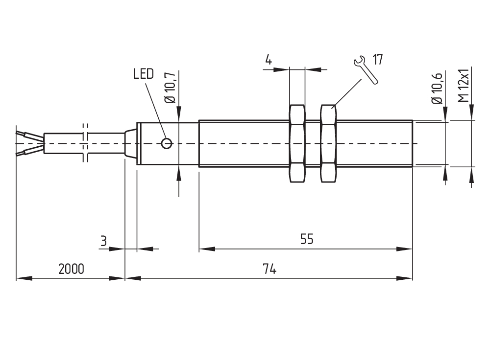
| ISO thread of the sensor |
M12 |
| width across flats |
17 BK |
| Length of sensor |
71 mm |
Ambient conditions
| Degree of protection |
IP67 |
| Ambient temperature |
-25 ... +70 °C |
| Resistance to vibrations |
10 … 55 Hz, amplitude 1 mm |
| Restistance to shock |
30 g / 11 ms |
| Protection class |
II |
Ambient conditions - Insulation values
| Rated impulse withstand voltage Uimp |
4 kV |
Electrical data
| Rated supply frequency, minimum |
45 Hz |
| Rated supply frequency, maximum |
65 Hz |
| Type of voltage range |
AC |
| Operating current, minimum |
8 mA |
| Rated operating voltage |
15 ... 250 VAC |
| Operating current |
200 mA |
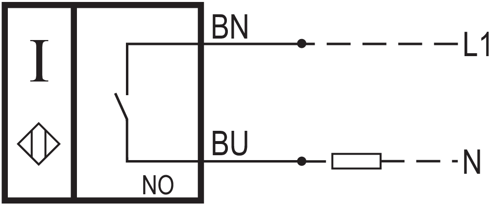
| Switching element |
Normally open contact (NO) |
| Protection circuit integrated |
inductive interference protection |
| Switching frequency, approx. |
10 Hz |
Electrical data - Digital Output
| Voltage drop Ud, maximum |
3.5 V |
| Current at Voltage drop Ud |
0.2 A |
| Design of control elements |
Two-wire |
| Current leakage Ir, maximum |
1 mA |
Status indication
| Note (Integral System Diagnostics, status ) |
yellow LED |
Note
| Note (General) |
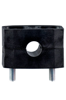
Instead of nuts, a mounting clamp can be provided. |
Language filter
Datasheet
Operating instructions (supplementary sheet/quick guide)
EC Declaration of conformity
CCC certification
Download the latest version of Adobe Reader
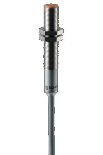
Product picture (catalogue individual photo)
Dimensional drawing basic component
| UK Declaration of Conformity |  |
| Company: | K.A. Schmersal GmbH & Co. KG Möddinghofe 30 42279 Wuppertal Germany Internet: www.schmersal.com |
| Declaration: | We hereby, under sole responsibility, certify that the hereafter described components both in their basic design and construction conform to the relevant statutory requirements, regulations and designated standards of the United Kingdom. |
| Name of the component: | IFL Design: Ø 4, Ø 6,5, Ø 20, Ø 40, M8, M12, M18, M30, 2.., 3.., 6.., R.. |
| Type: | See ordering code |
| Description of the component: | Inductive proximity switch |
| Relevant legislation: | Electrical Equipment (Safety) Regulations | 2016 |
| Electromagnetic Compatibility Regulations | 2016 | |
| The Restriction of the Use of Certain Hazardous Substances in Electrical and Electronic Equipment Regulations | 2012 |
| Designated standards: | EN IEC 60947-5-2:2020 |
| UK-Importer / Person authorised for the compilation of the technical documentation: | Schmersal UK Ltd. Paul Kenney Unit 1, Sparrowhawk Close Enigma Business Park Malvern, Worcestershire, WR14 1GL |
| Place and date of issue: | Wuppertal, January 16, 2023 |
 |
| Authorised signature Philip Schmersal Managing Director |
Schmersal India Pvt. Ltd., Plot No - G-7/1, Ranjangaon MIDC, Tal. - Shirur, Dist.- Pune 412 220
The details and data referred to have been carefully checked. Images may diverge from original. Further technical data can be found in the manual. Technical amendments and errors possible.
Generated on: 16/08/2025, 2:01 pm
.png?id=497683c97d2c2689df20070a5453bdbb)
