PROTECT-IE-11
PROTECT-IE-11
Downloads
| Product type description: PROTECT-IE-(1)-(2) |
| (1) | |
| 02 | 2 NC contact |
| 11 | 1 NO contact/1 NC contact |
| (2) | |
| without | Cage clamps |
| SK | Screw connection, plug-in |
- Input for up to 4 sensors per interface e.g.: magnetic safety switches type BNS, emergency stop devices, interlocking devices and others
- 2 safety contacts
Ordering data
| Product type description |
PROTECT-IE-11 |
| Article number (order number) |
101182805 |
| EAN (European Article Number) |
4250116202133 |
| eCl@ss number, version 12.0 |
27-37-18-19 |
| eCl@ss number, version 11.0 |
27-37-18-19 |
| eCl@ss number, version 9.0 |
27-37-18-19 |
| ETIM number, version 7.0 |
EC001449 |
| ETIM number, version 6.0 |
EC001449 |
| Notice |
Discontinued product |
General data
| Standards |
EN IEC 62061 EN ISO 13849-1 EN IEC 60947-5-1 EN IEC 60947-5-3 EN IEC 60947-5-5 EN IEC 61508 EN IEC 60204-1 EN IEC 60947-1 |
| Climatic stress |
EN 60068-2-78 |
| Housing material |
Glass-fibre reinforced thermoplastic, ventilated |
| Gross weight |
140 g |
General data - Features
| Electronic Fuse |
Yes |
| Wire breakage detection |
Yes |
| Cross-circuit detection |
Yes |
| Automatic reset function |
Yes |
| Earth connection detection |
Yes |
| Integral system diagnostics, general |
Yes |
| Number of auxiliary contacts |
1 |
| Number of LEDs |
5 |
| Number of normally closed (NC) |
1 |
| Number of normally open (NO) |
1 |
| Number of safety contacts |
2 |
| Safety classification |
| Vorschriften |
EN IEC 60947-5-1 EN IEC 61508 |
| Stop-Category |
0 |
| Safety classification - Relay outputs |
| Performance Level, up to |
d |
| Category |
3 |
| Diagnostic Coverage (DC) Level |
60 % |
| PFH value |
2.00 x 10⁻⁷ /h |
| Notice |
for max. 36,500 switching cycles/year and max. 60% contact load |
| Safety Integrity Level (SIL), suitable for applications in |
2 |
| Mission time |
20 Year(s) |
| Common Cause Failure (CCF), minimum |
65 |
Mechanical data
| Mechanical life, minimum |
10,000,000 Operations |
| Mounting |
Snaps onto standard DIN rail to EN 60715 |
Mechanical data - Connection technique
| Terminal designations |
IEC/EN 60947-1 |
| Termination |
Cage clamps |
| Cable section, minimum |
0.2 mm² |
| Cable section, maximum |
2.5 mm² |
Mechanical data - Dimensions
| Width |
48 mm |
| Height |
126 mm |
| Depth |
61 mm |
Ambient conditions
| Degree of protection of the enclosure |
IP20 |
| Degree of protection of the installation space |
IP20 |
| Degree of protection of clips or terminals |
IP20 |
| Ambient temperature |
-25 ... +55 °C |
| Storage and transport temperature |
-40 ... +85 °C |
| Resistance to vibrations |
10...55 Hz, Amplitude 0.35 mm, ± 15 % |
| Restistance to shock |
30 g / 11 ms |
Ambient conditions - Insulation values
| Rated impulse withstand voltage Uimp |
0.8 kV |
| Overvoltage category |
III |
| Degree of pollution |
2 |
Electrical data
| Operating voltage |
24 VDC -15 % / +20 % |
| Ripple voltage |
10 % |
| Rated operating voltage |
24 VDC |
| Rated AC voltage for controls at DC minimum |
20.4 VDC |
| Rated control voltage at DC, maximum |
28.8 VDC |
| Electrical power consumption |
1.7 W |
| Input resistance at Ue |
2,900 Ω |
| Contact resistance, maximum |
0.1 Ω |
| Note (Contact resistance) |
in new state |
| Drop-out delay in case of "emergency stop", maximum |
20 ms |
| Pull-in delay at automatic start, maximum |
20 ms |
Electrical data - Safe relay outputs
| Voltage, Utilisation category DC-13 |
24 VDC |
| Current, Utilisation category DC-13 |
2 A |
| Switching capacity, minimum |
10 VDC |
| Switching capacity, minimum |
10 mA |
| Switching capacity, maximum |
24 VAC |
| Switching capacity, maximum |
2 A |
Electrical data - Digital inputs
| Input signal, HIGH Signal "1" |
19 - 28,8 VDC |
| Input signal, LOW Signal "0" |
0 - 1 VDC |
| Conduction resistance, maximum |
40 Ω |
Electrical data - Digital Output
| Voltage, Utilisation category DC-12 |
24 VDC |
| Current, Utilisation category DC-12 |
0.1 A |
Electrical data - Relay outputs (auxiliary contacts)
| Switching capacity, maximum |
24 VDC |
| Switching capacity, maximum |
0.1 A |
Electrical data - Electromagnetic compatibility (EMC)
| EMC rating |
EMC-Directive |
Status indication
| Indicated operating states |
Position relay K2 Position relay K1 Position relay K3 Position relay K3 |
Other data
| Note (applications) |
Safety sensor Guard system Emergency-Stop button Pull-wire emergency stop switches |
Language filter
Datasheet
Operating instructions and Declaration of conformity
Download the latest version of Adobe Reader
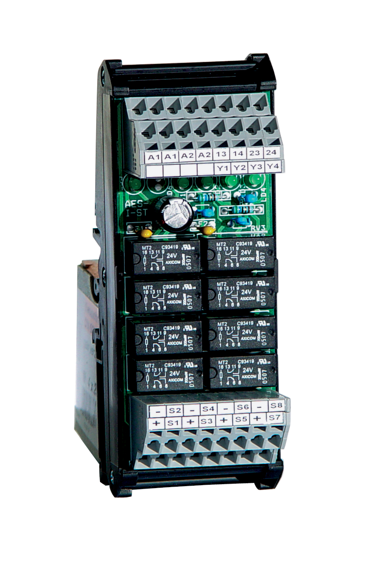
Product picture (catalogue individual photo)
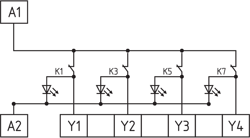
Wiring example

Wiring example
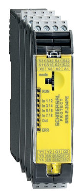
103008070 SRB-E-204PE
- Plug-in screw terminals with coding
- Input expander module
- 1 oder 2-channel control
- Monitoring of 4 sensors
- 2 Safety outputs
- 4 Signalling outputs

103009973 SRB-E-204ST
- Plug-in screw terminals with coding
- STOP 0 Function
- Monitoring of 4 sensors
- Start button / Auto-start
- 2 Safety outputs
- 4 Signalling outputs
| EU Declaration of Conformity |  |
| Original | K.A. Schmersal GmbH & Co. KG Möddinghofe 30 42279 Wuppertal Germany Internet: www.schmersal.com |
| Declaration: | We hereby certify that the hereafter described components both in their basic design and construction conform to the applicable European Directives. |
| Name of the component: | PROTECT-IE |
| Type: | See ordering code |
| Description of the component: | Safety-monitoring module as input expander in conjunction with a safety-monitoring module as basic device |
| Relevant Directives: | Machinery Directive | 2006/42/EC |
| EMC-Directive | 2014/30/EU | |
| RoHS-Directive | 2011/65/EU |
| Applied standards: | EN 60947-5-1:2004 + AC:2005 + A1:2009 EN 60947-5-1:2017 + AC:2020 EN ISO 13849-1:2015 EN ISO 13849-2:2012 EN 61326-3-1:2017 |
| Notified body, which approved the full quality assurance system, referred to in Appendix X, 2006/42/EC: | TÜV Rheinland Industrie Service GmbH Am Grauen Stein, 51105 Köln ID n°: 0035 |
| Person authorised for the compilation of the technical documentation: | Oliver Wacker Möddinghofe 30 42279 Wuppertal |
| Place and date of issue: | Wuppertal, March 21, 2023 |
 |
| Authorised signature Philip Schmersal Managing Director |
| UK Declaration of Conformity | |
| Company: | K.A. Schmersal GmbH & Co. KG Möddinghofe 30 42279 Wuppertal Germany Internet: www.schmersal.com |
| Declaration: | We hereby, under sole responsibility, certify that the hereafter described components both in their basic design and construction conform to the relevant statutory requirements, regulations and designated standards of the United Kingdom. |
| Name of the component: | PROTECT-IE |
| Type: | See ordering code |
| Description of the component: | Safety-monitoring module as input expander in conjunction with a safety-monitoring module as basic device |
| Relevant legislation: | Supply of Machinery (Safety) Regulations | 2008 |
| Electromagnetic Compatibility Regulations | 2016 | |
| The Restriction of the Use of Certain Hazardous Substances in Electrical and Electronic Equipment Regulations | 2012 |
| Designated standards: | EN 60947-5-1:2004 + AC:2005 + A1:2009 EN 60947-5-1:2017 + AC:2020 EN ISO 13849-1:2015 EN ISO 13849-2:2012 EN 61326-3-1:2017 |
| Notified body, which approved the full quality assurance system, referred to in Appendix X, 2006/42/EC: | TÜV Rheinland Industrie Service GmbH Am Grauen Stein 51105 Köln ID n°: 0035 |
| UK-Importer / Person authorised for the compilation of the technical documentation: | Schmersal UK Ltd. Paul Kenney Unit 1, Sparrowhawk Close Enigma Business Park Malvern, Worcestershire, WR14 1GL |
| Place and date of issue: | Wuppertal, March 21, 2023 |
|
| Authorised signature Philip Schmersal Managing Director |
Schmersal India Pvt. Ltd., Plot No - G-7/1, Ranjangaon MIDC, Tal. - Shirur, Dist.- Pune 412 220
The details and data referred to have been carefully checked. Images may diverge from original. Further technical data can be found in the manual. Technical amendments and errors possible.
Generated on: 06/08/2025, 7:30 am