SRB219IT-24VAC/DC
SRB219IT-24VAC/DC
Downloads
- Multifunctional safety relay module for superior diagnostics and visualisation
- Suitable for the signal processing of outputs with contact sensors
- Suitable for the signal processing of outputs with contact sensors
- Suitable for signal processing of outputs connected to potentials (AOPDs), e.g. safety light grids/curtains
- 1 + 8 Signalling outputs
- 2 safety contacts, STOP 0;
1 safety contact, STOP 1 (adjustable 1 … 30 s)
Ordering data
| Note (Delivery capacity) |
Not available! |
| Replacement article number |
101159512 |
| Product type description |
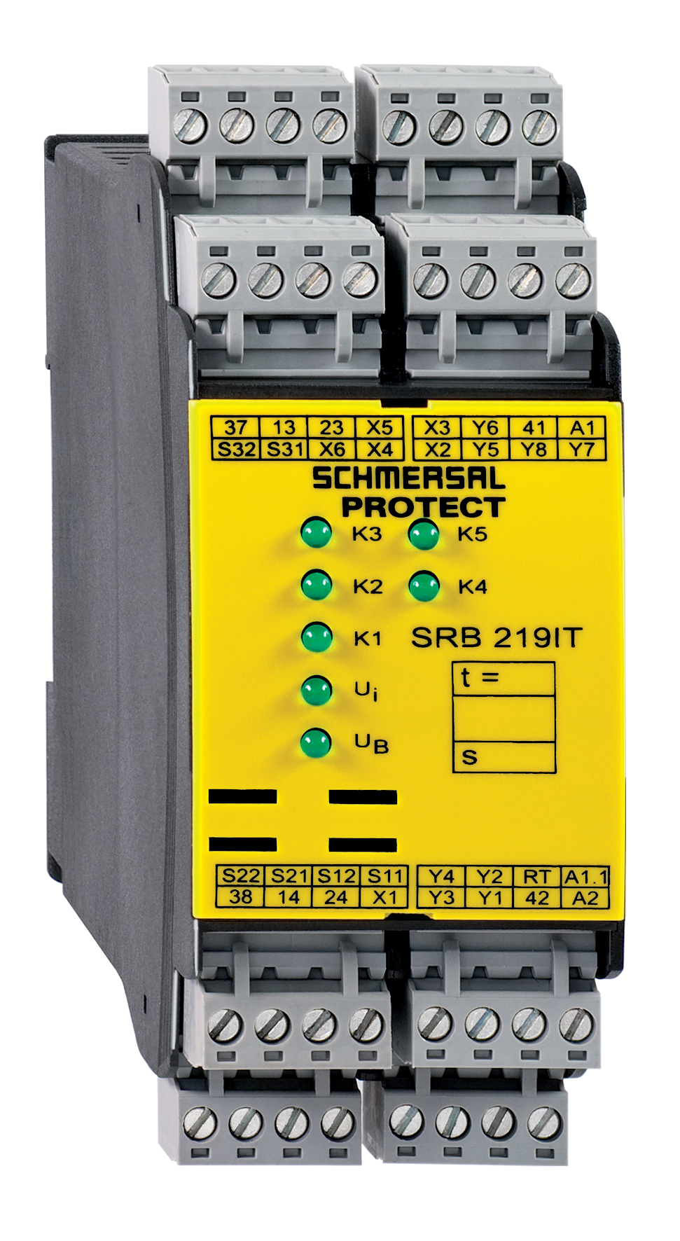
SRB219IT-24VAC/DC |
| Article number (order number) |
101158208 |
| EAN (European Article Number) |
4250116201570 |
| eCl@ss number, version 12.0 |
27-37-18-19 |
| eCl@ss number, version 11.0 |
27-37-18-19 |
| eCl@ss number, version 9.0 |
27-37-18-19 |
| ETIM number, version 7.0 |
EC001449 |
| ETIM number, version 6.0 |
EC001449 |
Approvals - Standards
| Certificates |
cULus |
General data
| Standards |
EN IEC 62061 EN ISO 13849-1 EN IEC 60947-5-1 EN IEC 60947-5-3 EN IEC 60947-5-5 EN IEC 61508 EN IEC 60204-1 EN IEC 60947-1 |
| Climatic stress |
EN 60068-2-78 |
| Housing material |
Glass-fibre reinforced thermoplastic, ventilated |
| Gross weight |
360 g |
General data - Features
| Electronic Fuse |
Yes |
| Wire breakage detection |
Yes |
| Cross-circuit detection |
Yes |
| Removable Terminals |
Yes |
| Start input |
Yes |
| Feedback circuit |
Yes |
| Automatic reset function |
Yes |
| Reset edge detection |
Yes |
| Earth connection detection |
Yes |
| Integral system diagnostics, status |
Yes |
| Number of auxiliary contacts |
1 |
| Number of LEDs |
7 |
| Number of normally closed (NC) |
2 |
| Number of undelayed semi-conductor outputs with signaling function |
7 |
| Number of delayed semi-conductor outputs with signaling function. |
1 |
| Number of safety contacts |
3 |
| Number of signalling outputs |
8 |
| Safety classification |
| Vorschriften |
EN IEC 60947-5-1 EN IEC 61508 |
| Stop-Category |
0 1 |
| Safety classification - Relay outputs |
| Performance Level, stop 0, up to |
e |
| Performance Level, stop 1, up to |
d |
| Category, Stop 0 |
4 |
| Category, Stop 1 |
3 |
| Diagnostic Coverage (DC) Level, Stop 0 |
≥ 99 % |
| Diagnostic Coverage (DC) Level, Stop 1 |
> 60 |
| PFH value, Stop 0 |
2.00 x 10⁻⁸ /h |
| PFH value, Stop 1 |
2.00 x 10⁻⁷ /h |
| Safety Integrity Level (SIL), Stop 0, suitable for applications in |
3 |
| Safety Integrity Level (SIL), Stop 1, suitable for applications in |
2 |
| Mission time |
20 Year(s) |
| Common Cause Failure (CCF), minimum |
65 |
Mechanical data
| Mechanical life, minimum |
10,000,000 Operations |
| Mounting |
Snaps onto standard DIN rail to EN 60715 |
Mechanical data - Connection technique
| Terminal designations |
IEC/EN 60947-1 |
| Termination |
rigid or flexible Screw terminals M20 x 1.5 |
| Cable section, minimum |
0.25 mm² |
| Cable section, maximum |
2.5 mm² |
| Tightening torque of Clips |
0.6 Nm |
Mechanical data - Dimensions
| Width |
45 mm |
| Height |
100 mm |
| Depth |
121 mm |
Ambient conditions
| Degree of protection of the enclosure |
IP40 |
| Degree of protection of the mounting space |
IP54 |
| Degree of protection of clips or terminals |
IP20 |
| Ambient temperature |
-25 ... +45 °C |
| Storage and transport temperature |
-40 ... +85 °C |
| Resistance to vibrations |
10...55 Hz, Amplitude 0.35 mm, ± 15 % |
| Restistance to shock |
30 g / 11 ms |
Ambient conditions - Insulation values
| Rated impulse withstand voltage Uimp |
4 kV |
| Overvoltage category |
III |
| Degree of pollution |
2 |
Electrical data
| Frequency range |
50 Hz 60 Hz |
| Operating voltage |
24 VAC -15 % / +10 % |
| Ripple voltage |
10 % |
| Rated operating voltage |
24 VAC |
| Rated operating voltage |
24 VDC |
| Operating current |
200 mA |
| Rated AC voltage for controls, 50 Hz, minimum |
20.4 VAC |
| Rated control voltage at AC 50 Hz, maximum |
26.4 VAC |
| Rated AC voltage for controls, 60 Hz, minimum |
20.4 VAC |
| Rated control voltage at AC 60 Hz, maximum |
26.4 VAC |
| Rated AC voltage for controls at DC minimum |
20.4 VDC |
| Rated control voltage at DC, maximum |
28.8 VDC |
| Electrical power consumption |
4.4 W |
| Electrical power consumption |
5.2 VA |
| Contact resistance, maximum |
0.1 Ω |
| Note (Contact resistance) |
in new state |
| Drop-out delay in case of "emergency stop", maximum |
15 ms |
| Pull-in delay at automatic start, maximum, typically |
60 ms |
| Pull-in delay at RESET, typically |
200 ms |
| Material of the contacts, electrical |
AgSn0. self-cleaning, positive drive |
Electrical data - Digital inputs
| Conduction resistance, maximum |
40 Ω |
Electrical data - Electromagnetic compatibility (EMC)
| EMC rating |
EMC-Directive |
Status indication
| Indicated operating states |
Position relay K2 Position relay K1 Internal operating voltage Ui Position relay K3 Position relay K5 |
Other data
| Note (applications) |
Safety sensor Guard system Emergency-Stop button Pull-wire emergency stop switches Safety light curtain |
Note
| Note (General) |
Inductive loads (e.g. contactors, relays, etc.) are to be suppressed by means of a suitable circuit. |
Wiring example
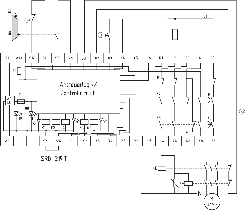
| Note (Wiring diagram) |
The wiring diagram is shown with guard doors closed and in de-energised condition. The ISD tables (Intergral System Diagnostics) for analysis of the fault indications and their causes are shown in the appendix. The control system recognises wire-breakage and earth faults in the monitoring circuit. Relay outputs: Suitable for 2 channel control, for increase in capacity or number of contacts by means of contactors or relays with positive-guided contacts. Connect potential p-type outputs of safety light grids/curtains to S12/S22. The devices must have the same reference potential. Time delay: The time-delayed safety enable 37/38 is adjustable for 1 to 30 seconds drop-out delay (see setting intructions). Setting of the drop-out delay time is carried out by means of a potentiometer from the front of the enclosure. For 2-channel control with cross-wire monitoring, connect the NC contact to S11/S12 and S31/S32 and bridge S21/S22 "Start function / Reset button: The function "trailing edge" is programmed by means of the "AF" switch located underneath the housing cover (switch position = 1). The automatic start is programmed by bridging terminals X3/X5 and by switching the "AF" switch to 0. The time offset between the channels is approx. 100 ms. An endless time offset between the channels 1 and 2 is programmed by bridging the terminals X3/X6." Input level: The example shows a 2-channel control of a guard door monitoring with two position switches, whereof one with positive break, external reset button (R) and feedback circuit (H2). (example without cross-wire monitoring) For 1-channel control, connect NC contact to S11/S12 and bridge S21/S22 + S31/S32 Early switch-off of time delay: The drop-out delay time can be ended early via the input RT. The input RT makes it possible to "switch off" the time-delayed enabling circuit 37/38 before the set time has elapsed." F1 = Hybrid fuse F2 = Fuse for signalling outputs |
Language filter
Datasheet
Operating instructions and Declaration of conformity
UL Certificate
Wiring example (electr. wiring)
Force-travel diagram
Download the latest version of Adobe Reader
Product picture (catalogue individual photo)
Wiring example
Symbol (technical standard)

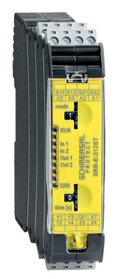
103007222 SRB-E-212ST
- Plug-in screw terminals with coding
- STOP 0 / 1 Function
- 1 oder 2-channel control
- 2 safety contacts STOP 0
- 1 Safety output STOP 1
- Drop-out delay adjustable in steps 0 … 30
K.A. Schmersal GmbH & Co. KG, Möddinghofe 30, 42279 Wuppertal
The details and data referred to have been carefully checked. Images may diverge from original. Further technical data can be found in the manual. Technical amendments and errors possible.
Generated on: 01/06/2025, 18:09