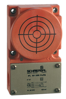
BN 310-RZ

BN 310-RZ
- 1 Reed contakts
- Non-contact principle
- Actuation from side
- Flat design
- Actuating surface and direction of actuation marked by switch symbol
- 88 mm x 25 mm x 13 mm
- Thermoplastic enclosure
- Actuating distance up to 60 mm depending on actuating magnet and version
- 2 reed contacts
Ordering data
| Product type description |
BN 310-RZ |
| Article number (order number) |
101133843 |
| EAN (European Article Number) |
4030661059426 |
| eCl@ss number, version 12.0 |
27-27-43-02 |
| eCl@ss number, version 11.0 |
27-27-01-05 |
| eCl@ss number, version 9.0 |
27-27-01-05 |
| ETIM number, version 7.0 |
EC002544 |
| ETIM number, version 6.0 |
EC002544 |
Approvals - Standards
| Certificates |
cULus |
General data
| Working principle |
magnetico |
| Housing construction form |
rettangolare |
| Housing material |
materiale sintetico, termoplastica rinforzata con fibra di vetro |
| Gross weight |
65 g |
General data - Features
| Latching |
Sì |
| Suitable for elevators |
Sì |
| Number of snap-in contacts |
1 |
Mechanical data
| Actuating panels |
lateralmente |
| Actuating element |
magnete |
| Mechanical life, minimum |
1.000.000.000 Operations |
| Actuating speed, maximum |
18 m/s |
| Mounting |
Custodie con asole allungate |
Mechanical data - Switching distances
| Switching distance Sn |
BP 10N = 15 mm BP 10S = 15 mm 2 x BP 10N = 20 mm 2 x BP 10S = 20 mm BP 15N = 17 mm BP 15S = 17 mm 2 x BP 15/2N = 22 mm 2 x BP 15/2S = 22 mm BP 34S = 15 ... 30 mm BP 11N = 15 mm BP 11S = 15 mm BP 12N = 20 mm BP 12S = 20 mm 2 x BP 12N = 10 ... 30 mm 2 x BP 12S = 10 ... 30 mm BP 21N = 15 ... 45 mm BP 21S = 15 ... 45 mm 2 x BP 21N = 20 ... 60 mm 2 x BP 21S = 20 ... 60 mm BE 20N = 20 mm BE 20S = 20 mm 5 mm … 60 mm BP 34N = 15 ... 30 mm BP 20N = 3 ... 25 mm BP 20S = 3 ... 25 mm BP 31N = 3 ... 25 mm BP 31S = 3 ... 25 mm 2 x BP 11N = 3 ... 25 mm 2 x BP 11S = 3 ... 25 mm |
| Note (Switching distance Sn) |
Distanza di commutazione fino a 60 mm, dipendente dal magnete di azionamento e versione. I dati relativi alle distanze di commutazione sono validi per l'azionamento di dispositivi montati singolarmente senza influenza ferromagnetica. Una eventuale influenza ferromagnetica può determinare un'alterazione della distanza, positiva o negativa. In caso di allineamento di diversi magneti di azionamento è necessario prendere in considerazione la relativa influenza reciproca. |
| Note (switching distance) |
All switching distances in accordance EN IEC 60947-5-2 |
| Repeat accuracy R |
0,3 mm |
Mechanical data - Connection technique
| Length of cable |
1 m |
| Termination |
cavo |
| Wire cross-section |
0,75 mm2 |
| Wire cross-section |
18 AWG |
| Material of the Cable mantle |
H03VV-F |
Mechanical data - Dimensions
| Length of sensor |
13 mm |
| Width of sensor |
88 mm |
| Height of sensor |
25 mm |
Ambient conditions
| Degree of protection |
IP67 |
| Ambient temperature |
-25 ... +75 °C |
| Resistance to vibrations |
10…55 Hz, ampiezza 1 mm |
| Restistance to shock |
30 g / 11 ms |
Electrical data
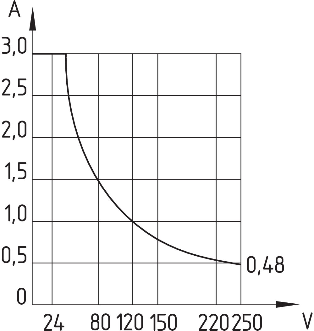
| Switching voltage, maximum |
250 VAC |
| Switching voltage, maximum |
250 VDC |
| Switching current, maximum |
3 A |
| Switching capacity, maximum |
120 W |
| Switching capacity, maximum |
120 VA |
| Switching element |
commutatore bistabile |
| Bounce duration, minimum |
0,3 ms |
| Bounce duration, maximum |
0,6 ms |
| Switching frequency, maximum |
300 Hz |
Electrical data - Digital Output
| Design of control elements |
contatti reed |
Scope of delivery
| Scope of delivery |
Actuator must be ordered separately. |
Accessory
| Recommendation (actuator) |
BP 10 S 2x BP 10 S BP 15 S BP 34 S BP 20 S BP 31 S BP 11 S 2x BP 11 S BP 12 S BP 21 S 2x BP 21 S BP 10 N 2x BP 10 N BP 15 N 2 x BP 15/2 N 2x BP 15/2 S BP 34 N BP 20 N BP 31 N BP 11 N 2x BP 11 N BP 12 N 2x BP 12 N 2x BP 12 S BP 21 N 2x BP 21 N BE 20 N(S) ST 24VDC BE 20 N(S) 48VDC |
| Recommendation (actuator, lift switchgear) |
BP 10 2 x BP 15/2 2 x BP 15 2 x BP 10 BP 15 BP 34 |
Note
| Note (General) |
La funzione di apertura e di chiusura dipende dalla direzione di azionamento, dal magnete di azionamento e dalla polarità del magnete di azionamento. Ponendo di fronte l'interruttore ed il magnete di azionamento devono corrispondere gli abbinamenti di colori: rosso (S) su rosso (S) e verde (N) su verde (N). Questo non vale con il bistabile. L’interruttore va montato su ferro con uno spessore di materiale non magnetico non inferiore a 20 mm. |
Filtro lingua
Scheda Tecnica
Manuale d'istruzioni (Inserto/Guida rapida)
Dichiarazione di conformità UE
Certificazione UL
Informazioni
Download dell'ultima versione di Adobe Reader
Immagine del prodotto (foto singola per catalogo)

ID: kbn31f04
| 98,1 kB | .jpg | 352.778 x 97.719 mm - 1000 x 277 px - 72 dpi
| 13,9 kB | .png | 74.083 x 20.461 mm - 210 x 58 px - 72 dpi
| 90,9 kB | .jpg | 352.778 x 97.719 mm - 1000 x 277 px - 72 dpi
| 12,4 kB | .png | 74.083 x 20.461 mm - 210 x 58 px - 72 dpi
| 15,3 kB | .jpg | 123.472 x 34.219 mm - 350 x 97 px - 72 dpi
Disegno quotato disp. di base

Diagramma della corsa di azionamento

Diagramma della corsa di azionamento
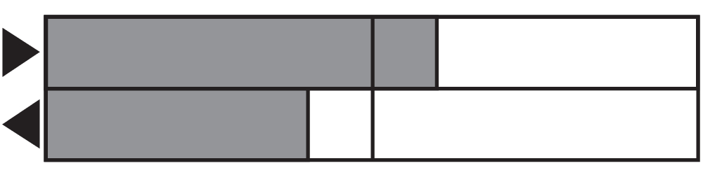
Schema contatti
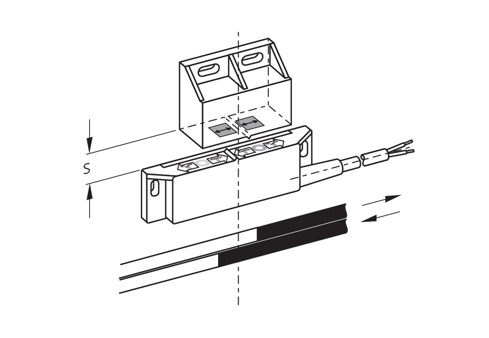
Diagramma curve caratteristiche


Schmersal India Pvt. Ltd., Plot No - G-7/1, Ranjangaon MIDC, Tal. - Shirur, Dist.- Pune 412 220
I dettagli e i dati qui riportati sono stati attentamente verificati. Le immagini possono differire dagli originali. Altri dati tecnici possono essere trovati nei manuali. Salvo modifiche tecniche o errori.
Generato il 14/04/2025, 11:55
Visti di recente