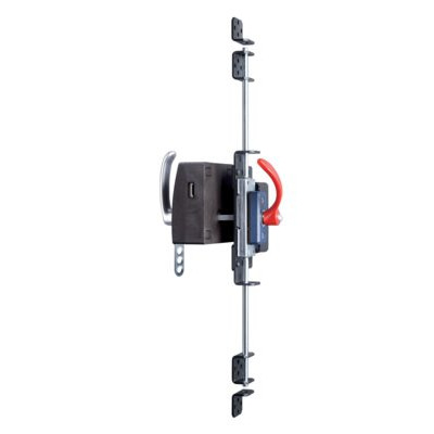
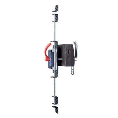
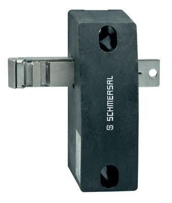
AZM201Z-CC-T-1P2PW
AZM201Z-CC-T-1P2PW
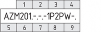
| Typebenaming van het product: AZM201(1)-(2)-(3)-T-(4)-(5) |
| (1) | |
| Z | Bewaking van de veiligheidsvergrendeling |
| B | Bewaking van de bediensleutel |
| (2) | |
| zonder | Standaard codering |
| I1 | Individuele codering |
| I2 | Individuele codering, meerdere keren aanleerbaar |
| (3) | |
| SK | Schroefaansluitklemmen |
| CC | Veeraansluitklemmen |
| ST2 | Inbouwstekker M12, 8-polig |
| (4) | |
| 1P2PW | 1 diagnose-uitgang, met p-schakeling en >2 veiligheidsuitgangen, met p-schakeling>(gecombineerd diagnosesignaal: beschermvoorziening gesloten en vergrendeling vergrendeld) |
| SD2P | seriële diagnose-uitgang en 2 veiligheidsuitgangen met p-schakeling |
| (5) | |
| zonder | ruststroomprincipe |
| A | arbeidsstroomprincipe |
- ruststroomprincipe
- Bewaking van de vergrendeling
- Kunststofbehuizing
- Max. lengte van de sensorketting 200 m
- Zelfbewakende serieschakeling
- Codering volgens ISO 14119 via RFID-technologie
- 3 LEDs ter weergave van de bedrijfsstatus
- De sensortechnologie laat een afwijking tussen de bediensleutel en de veiligheidsvergrendeling toe van ± 5 mm verticaal en ± 1,5 mm horizontaal
- Geschikt voor draai- en schuifdeuren
- Intelligente diagnose
- hulpontgrendeling
- Afdichtingsgraad IP66, IP67
- Hoge vasthoudkracht 2000 N
- symmetrisch bouwvorm, montage op 40mm profielen
- OSSD-Veiligheidsuitgangen
- Paniekontgrendeling / Noodontgrendeling los verkrijgbaar
Bestelvoorbeeld
| Typebenaming van het product |
AZM201Z-CC-T-1P2PW |
| Artikelnummer (bestelnummer) |
103013912 |
| EAN (Europees Artikel Nummer) |
4030661493404 |
| eCl@ss nummer, versie 12.0 |
27-27-26-03 |
| eCl@ss nummer, versie 11.0 |
27-27-26-03 |
| eCl@ss nummer, versie 9.0 |
27-27-26-03 |
| ETIM-nummer, versie 7.0 |
EC002593 |
| ETIM-nummer, versie 6.0 |
EC002593 |
Certificeringen - Voorschriften
|
TÜV cULus FCC IC UKCA ANATEL |
Algemene gegevens
| Voorschriften |
EN ISO 13849-1 EN ISO 14119 EN IEC 60947-5-3 EN IEC 61508 |
| algemene informatie |
Universele codering |
| Codeerniveau volgens EN ISO 14119 |
gering |
| Werkingsprincipe |
RFID |
| Frequentieband RFID |
125 kHz |
| Zendvermogen RFID, maximum |
-6 dBm |
| Materiaal van de behuizing |
Kunststof, glasvezelversterkte thermoplast |
| Risicotijd, maximum |
200 ms |
Reactietijd van de veiligheidsuitgangen in geval van uitschakeling door de actuator, maximaal |
100 ms |
Reactietijd van de veiligheidsuitgangen bij uitschakeling door de veiligheidsingangen, maximaal |
1,5 ms |
| Brutogewicht |
566 g |
Algemene gegevens - Eigenschappen
| ruststroomprincipe |
Ja |
| Bewaking van de vergrendeling |
Ja |
| hulpontgrendeling |
Ja |
| Kortsluitdetectie mogelijk |
Ja |
| Dwarssluitingsherkenning |
Ja |
| Serieschakeling |
Ja |
| Veiligheidsfuncties |
Ja |
| Geïntegreerde weergave, status |
Ja |
| Aantal veiligheidscontacten |
2 |
Classificatie
| Voorschriften |
EN ISO 13849-1 EN IEC 61508 |
Veiligheidsclassificatie - Arrêteerfunctie
| Performance Level, tot |
e |
| Sturingscategorie |
4 |
| PFH waarde |
1,90 x 10⁻⁹ /h |
| PFD waarde |
1,60 x 10⁻⁴ |
| Safety Integrity Level (SIL), geschikt voor toepassingen in |
3 |
| Gebruiksduur |
20 Jaar (Jaren) |
Veiligheidsclassificatie - Vergrendelfunctie
| Performance Level, tot |
d |
| Sturingscategorie |
2 |
| PFH waarde |
1,00 x 10⁻⁸ /h |
| PFD waarde |
8,90 x 10⁻⁴ |
| Safety Integrity Level (SIL), geschikt voor toepassingen in |
2 |
| Gebruiksduur |
20 Jaar (Jaren) |
Mechanische gegevens
| Mechanische levensduurduur, minimum |
1.000.000 schakelingen |
| Blokkeerkracht FZh volgens IOS14119 |
2.000 N |
| Opmerking (blokkeerkracht FZh) |
1,000 N when used with the AZ/AZM201-B30 actuator, for indoor use. |
| Blokkeerkracht Fmax, maximum |
2.600 N |
| Opmerking (blokkeerkracht Fmax) |
1.300 N in Verbindung mit einem Betätiger AZ/AZM201-B30 für Innenanbau. |
| Arrêteerkracht |
30 N |
| Max. bedieningssnelheid |
0,2 m/s |
| Uitvoering van de bevestigingsschroeven |
2x M6 |
| Aandraaimoment van de bevestigingsschroeven, maximum |
8 Nm |
| Aandraaimoment voor de bevestigingsschroeven van het toesteldeksel, minimum |
0,7 Nm |
| Aandraaimoment voor de bevestigingsschroeven van het toesteldeksel, maximum |
1 Nm |
| Opmerking |
Torx T10 |
Mechanische gegevens - Aansluittechniek
| Lengte van de sensorketting, maximum |
200 m |
| Opmerking (Lengte van de sensorketting) |
Cable length and cross-section change the voltage drop dependiing on the output current |
| Opmerking (Serieschakeling) |
Unlimited number of devices, oberserve external line fusing, max. 31 devices in case of serial diagnostic SD |
| Kabelingang |
1 x M20 |
| aansluitwijze |
Veerklemaansluiting |
| Draaddoorsnede, minimum |
0,25 mm² |
| Kabeldoorsnede, maximum |
1,5 mm² |
| Opmerking |
Alle specificaties inclusief adereindhulzen. |
| Aderdoorsnede, minimum |
23 AWG |
| Aderdoorsnede, maximum |
15 AWG |
| Toegelaten kabeltype |
solid single-wire solid multi-wire flexible |
Mechanische gegevens - Afmetingen
| Lengte van de sensor |
50 mm |
| Breedte van de sensor |
40 mm |
| Hoogte van de sensor |
220 mm |
Omgevingsvoorwaarden
| Afdichtingsgraad |
IP66 IP67 |
| Omgevingstemperatuur |
-25 ... +60 °C |
| Opslag- en transporttemperatuur |
-25 ... +85 °C |
| Relatieve vochtigheid, maximum |
93 % |
| Opmerking (relatieve vochtigheid) |
niet-condenserend geen berijping |
| Trillingsvastheid |
10 … 150 Hz, Amplitude 0,35 mm |
| schokbestendig |
30 g / 11 ms |
| Beschermklasse |
III |
| Toegelaten opstelhoogte boven NN, maximum |
2.000 m |
Omgevingsvoorwaarden - Isolatieparameters
| Nominale isolatiespanning Ui |
32 VDC |
| Nominale impulsspanningsvastheid Uimp |
0,8 kV |
| Overspanningscategorie |
III |
| Vervuilingsgraad |
3 |
Elektrische gegevens
| Bedrijfsspanning |
24 VDC -15 % / +10 % |
| Nullaststroom I0, typisch |
50 mA |
| Stroomverbruik bij magneet AAN, gemiddelde waarde |
200 mA |
| Stroomverbruik bij magneet AAN, piekwaarde |
700 mA / 100 ms |
| Nominale bedrijfsspanning |
24 VDC |
| Nominale bedrijfsstroom |
1.200 mA |
| Voorwaardelijke nominale kortsluitstroom |
100 A |
| Externe kabelbeveiliging en toestelzekering |
4A gG |
| Tijd voor operationeel, maximum |
4.000 ms |
| Schakelfrequentie, maximum |
1 Hz |
Elektrische gegevens - magneetaansturing IN
| Benaming, magneetaansturing |
IN |
| Schakeldrempels |
-3 V … 5 V (Low) 15 V … 30 V (High) |
| Stroomverbruik bij 24 V |
10 mA |
| Inschakelduur magneet |
100 % |
| Testimpulsduur, maximum |
5 ms |
| Testimpulsinterval, minimum |
40 ms |
| Classificatie ZVEI CB24I, daling |
C0 |
| Classificatie ZVEI CB24I, bron |
C1 C2 C3 |
Elektrische gegevens - Veilige analoge ingangen
| Benaming, veiligheidsingangen |
X1 en X2 |
| Schakeldrempels |
−3 V … 5 V (Low) 15 V … 30 V (High) |
| Stroomverbruik bij 24 V |
5 mA |
| Testimpulsduur, maximum |
1 ms |
| Testimpulsinterval, minimum |
100 ms |
| Classificatie ZVEI CB24I, daling |
C1 |
| Classificatie ZVEI CB24I, bron |
C1 C2 C3 |
Elektrische gegevens - Veilige digitale uitgangen
| Benaming, veiligheidsuitgangen |
Y1 en Y2 |
| Nominale bedrijfsstroom (veiligheidsuitgangen) |
250 mA |
| Uitvoering van de schakelelementen |
kortsluitvast, p-schakelend |
| Spanningsval Ud, maximum |
2 V |
| Lekstroom Ir, maximum |
0,5 mA |
| Spanning, gebruikscategorie DC-13 |
24 VDC |
| Stroom, gebruikscategorie DC-13 |
0,25 A |
| Testimpulsinterval, typisch |
1000 ms |
| Testimpulsduur, maximum |
0,5 ms |
| Classificatie ZVEI CB24I, bron |
C2 |
| Classificatie ZVEI CB24I, daling |
C1 C2 |
Elektrische gegevens - Diagnose-uitgang
| Benaming, Diagnose-uitgangen |
OUT |
| Nominale bedrijfsstroom |
50 mA |
| Uitvoering van de schakelelementen |
kortsluitvast, p-schakelend |
| Spanningsval Ud, maximum |
4 V |
| Spanning, gebruikscategorie DC-13 |
24 VDC |
| Stroom, gebruikscategorie DC-13 |
0,05 A |
Statusindicatie
| Opmerking (LED-statusindicatie) |
Bedrijfstoestand: gele LED Fout / functiestoring: rode LED Voedingsspanning UB: groene LED |
Leveringsomvang
| Leveringsomvang |
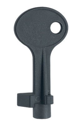
Actuator must be ordered separately. Driekantsleutel für AZM 201 |
Toebehoren
| Aanbeveling (bediensleutel) |
AZ/AZM201-B1 AZ/AZM201-B30 |
Opmerking
| Opmerking (algemeen) |
Zolang de bedieneenheid in de veiligheidsvergrendeling ingevoerd blijft, kan de ontgrendelde beschermvoorziening opnieuw vergrendeld worden. De veiligheidsuitgangen worden dan opnieuw ingeschakeld, zodat de beschermvoorziening niet geopend moet worden. |
Taalfilter
Datasheet
Bedieningshandleiding (bijlage/beknopte handleiding)
Bedieningshandleiding en conformiteitsverklaring (Short)
UL-certificaat
IC-Zertifikat
ANATEL-certificaat
Brochure
SISTEMA-VDMA-bibliotheek/library
Download de nieuwste versie van Adobe Reader
Foto van het product (individuele catalogusfoto)
Maatschets basistoestel
Schakelvoorbeeld
Video ID: AZM200-Anschluss1
Aansluiting een toestel (Vimeo)

Video ID: AZM200-Anschluss2
Aansluiting serieschakeling (Vimeo)
Video ID: AZM200-Betrieb1
Standard Betrieb (Vimeo)
Video ID: AZM200-Betrieb2
Paniekontgrendeling (Vimeo)
Video ID: AZM200-Betrieb3
Gecontroleerd uitschakelproces in geval van dwarssluiting (Vimeo)
Video ID: AZM200-Intro
Variabele montagemogelijkheden (Vimeo)
Video ID: AZM200-Montage1
Montage zonder paniekontgrendeling (Vimeo)
Video ID: AZM200-Montage2
Montage met paniekontgrendeling (Vimeo)

103009970 SRB-E-201LC
- Steekbare schroefklemmen met codering
- STOP 0 Functie
- 1 oder 2-kanalige aansturing
- Startknop / Autostart
- 2 Veiligheidsuitgangen 2 A
- 1 Signaaluitgang

103007672 SRB-E-301ST
- Steekbare schroefklemmen met codering
- STOP 0 Functie
- 1 oder 2-kanalige aansturing
- Startknop / Autostart
- 1 Hulpcontact
- 3 veiligheidscontacten

103009973 SRB-E-204ST
- Steekbare schroefklemmen met codering
- STOP 0 Functie
- Bewaking van 4 sensoren
- Startknop / Autostart
- 2 Veiligheidsuitgangen
- 4 Signaaluitgangen

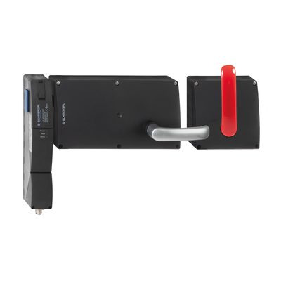
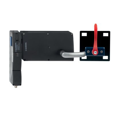
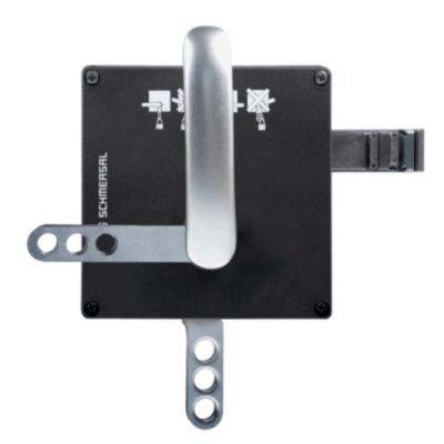
103013501 AZ/AZM201-B30-LTAG1
- voor deuren met aanslag links
- met deurhandgreep
- Bediensleutel voor draaibare beschermvoorzieningen
- Gemakkelijke en intuïtieve bediening
- Geen gevaar voor verwonding door uitstekende bediensleutel
- Geen bijkomende deurgrepen vereist
- Steekt niet uit in de deuropening
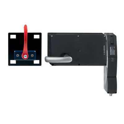
103013502 AZ/AZM201-B30-RTAG1
- voor deuren met aanslag rechts
- met deurhandgreep
- Bediensleutel voor draaibare beschermvoorzieningen
- Gemakkelijke en intuïtieve bediening
- Geen gevaar voor verwonding door uitstekende bediensleutel
- Geen bijkomende deurgrepen vereist
- Steekt niet uit in de deuropening

103013498 AZ/AZM201-B30-LTAG1P1
- voor deuren met aanslag links
- met deurhandgreep en ontsnappingshandgreep
- Bediensleutel voor draaibare beschermvoorzieningen
- Gemakkelijke en intuïtieve bediening
- Geen gevaar voor verwonding door uitstekende bediensleutel
- Geen bijkomende deurgrepen vereist
- Steekt niet uit in de deuropening
103013497 AZ/AZM201-B30-RTAG1P1
- voor deuren met aanslag rechts
- met deurhandgreep en ontsnappingshandgreep
- Bediensleutel voor draaibare beschermvoorzieningen
- Gemakkelijke en intuïtieve bediening
- Geen gevaar voor verwonding door uitstekende bediensleutel
- Geen bijkomende deurgrepen vereist
- Steekt niet uit in de deuropening
103013500 AZ/AZM201-B30-LTAG1P1-SZ
- voor deuren met aanslag links
- met deurhandgreep en ontsnappingshandgreep
- met geïntegreerde spertang
- Bediensleutel voor draaibare beschermvoorzieningen
- Gemakkelijke en intuïtieve bediening
- Geen gevaar voor verwonding door uitstekende bediensleutel
- Geen bijkomende deurgrepen vereist
- Steekt niet uit in de deuropening
103013499 AZ/AZM201-B30-RTAG1P1-SZ
- voor deuren met aanslag rechts
- met deurhandgreep en ontsnappingshandgreep
- met geïntegreerde spertang
- Bediensleutel voor draaibare beschermvoorzieningen
- Gemakkelijke en intuïtieve bediening
- Geen gevaar voor verwonding door uitstekende bediensleutel
- Geen bijkomende deurgrepen vereist
- Steekt niet uit in de deuropening
103026322 AZ/AZM201-B30-LTAG1P20-SZ
- met geïntegreerde spertang
- Geen bijkomende deurgrepen vereist
- voor deuren met aanslag links
- Gemakkelijke en intuïtieve bediening
- Steekt niet uit in de deuropening
- Bediensleutel voor draaibare beschermvoorzieningen
- met deurhandgreep en ontsnappingshandgreep
- Geen gevaar voor verwonding door uitstekende bediensleutel
103026321 AZ/AZM201-B30-RTAG1P20-SZ
- met geïntegreerde spertang
- Geen bijkomende deurgrepen vereist
- voor deuren met aanslag rechts
- Gemakkelijke en intuïtieve bediening
- Steekt niet uit in de deuropening
- Bediensleutel voor draaibare beschermvoorzieningen
- met deurhandgreep en ontsnappingshandgreep
- Geen gevaar voor verwonding door uitstekende bediensleutel
103015820 AZ/AZM201-B30-LTAG1P30
- voor deuren met aanslag links
- met deurhandgreep
- Bediensleutel voor draaibare beschermvoorzieningen
- Gemakkelijke en intuïtieve bediening
- Geen gevaar voor verwonding door uitstekende bediensleutel
- Geen bijkomende deurgrepen vereist
- Steekt niet uit in de deuropening
103015823 AZ/AZM201-B30-RTAG1P30
- voor deuren met aanslag rechts
- met deurhandgreep
- Bediensleutel voor draaibare beschermvoorzieningen
- Gemakkelijke en intuïtieve bediening
- Geen gevaar voor verwonding door uitstekende bediensleutel
- Geen bijkomende deurgrepen vereist
- Steekt niet uit in de deuropening
103015821 AZ/AZM201-B30-LTAG1P31
- voor deuren met aanslag links
- met deurhandgreep en ontsnappingshandgreep
- Bediensleutel voor draaibare beschermvoorzieningen
- Gemakkelijke en intuïtieve bediening
- Geen gevaar voor verwonding door uitstekende bediensleutel
- Geen bijkomende deurgrepen vereist
- Steekt niet uit in de deuropening

103015824 AZ/AZM201-B30-RTAG1P31
- voor deuren met aanslag rechts
- met deurhandgreep en ontsnappingshandgreep
- Bediensleutel voor draaibare beschermvoorzieningen
- Gemakkelijke en intuïtieve bediening
- Geen gevaar voor verwonding door uitstekende bediensleutel
- Geen bijkomende deurgrepen vereist
- Steekt niet uit in de deuropening
103015822 AZ/AZM201-B30-LTAG1P31-SZ
- voor deuren met aanslag links
- met deurhandgreep en ontsnappingshandgreep
- met geïntegreerde spertang
- Bediensleutel voor draaibare beschermvoorzieningen
- Gemakkelijke en intuïtieve bediening
- Geen gevaar voor verwonding door uitstekende bediensleutel
- Geen bijkomende deurgrepen vereist
- Steekt niet uit in de deuropening
103015825 AZ/AZM201-B30-RTAG1P31-SZ
- voor deuren met aanslag rechts
- met deurhandgreep en ontsnappingshandgreep
- met geïntegreerde spertang
- Bediensleutel voor draaibare beschermvoorzieningen
- Gemakkelijke en intuïtieve bediening
- Geen gevaar voor verwonding door uitstekende bediensleutel
- Geen bijkomende deurgrepen vereist
- Steekt niet uit in de deuropening

103013493 AZ/AZM201-B1-LT
- voor deuren met aanslag links
- Verend gelagerde bedieningssleutel
- Bediensleutel voor verplaatsbare beschermvoorzieningen
- Veerslaghoogte tot max. 5 mm
103013496 AZ/AZM201-B1-LTP0
- voor deuren met aanslag links
- met Paniekontgrendeling
- Verend gelagerde bedieningssleutel
- Bediensleutel voor verplaatsbare beschermvoorzieningen
- Veerslaghoogte tot max. 5 mm
103013494 AZ/AZM201-B1-RT
- voor deuren met aanslag rechts
- Verend gelagerde bedieningssleutel
- Bediensleutel voor verplaatsbare beschermvoorzieningen
- Veerslaghoogte tot max. 5 mm
103013495 AZ/AZM201-B1-RTP0
- voor deuren met aanslag rechts
- met Paniekontgrendeling
- Verend gelagerde bedieningssleutel
- Bediensleutel voor verplaatsbare beschermvoorzieningen
- Veerslaghoogte tot max. 5 mm


103004966 RF-AZM201-T
- Ombouwkit paniekontgrendeling
- De ombouwkit dient voor de latere functie-uitbreiding van de veiligheidsvergrendeling AZM 201
103003543 RF-AZM201-N
- Ombouwkit noodontgrendeling
- De ombouwkit dient voor de latere functie-uitbreiding van de veiligheidsvergrendeling AZM 201
- optionele soldering mogelijk
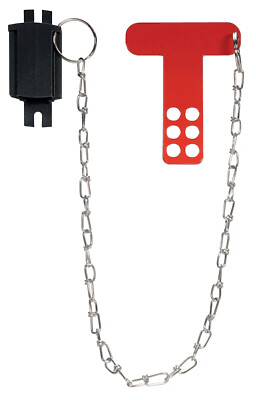
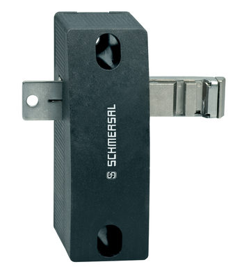
103051655 SZ201-1
- Geschikt voor montage binnen en buiten de gevarenzone
- Als beveiliging tegen onopzettelijk sluiten, bijvoorbeeld bij montagewerken
- Voor onoverzichtelijke installaties
- Verhindert bediening van de schakelaar
- Spertang met 6 boorgaten
101194438 SPERRZANGE SZ 200
- Spertang met 5 boorgaten
- Geschikt voor montage binnen en buiten de gevarenzone
- Als beveiliging tegen onopzettelijk sluiten, bijvoorbeeld bij montagewerken
- Voor onoverzichtelijke installaties
- Verhindert bediening van de schakelaar
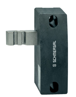
103001074 RF-AZ/AZM201-B30-SZ
- maakt het mogelijk om achteraf een geïntegreerde sluitklem te monteren
- geschikt voor bestaande B30-actuatorsystemen
- Spertang met 3 boorgaten
- Voor onoverzichtelijke installaties
- Verhindert bediening van de schakelaar
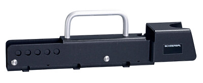
101166329 TFI-010
- Voorpositionering
- De bedieningssleutel is onafhankelijk van de centreerhulp
- Gemakkelijk in- of uitschuiven van de bedieningssleutel
101166328 TFA-010
- Voorpositionering
- De bedieningssleutel is onafhankelijk van de centreerhulp
- Gemakkelijk in- of uitschuiven van de bedieningssleutel
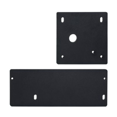
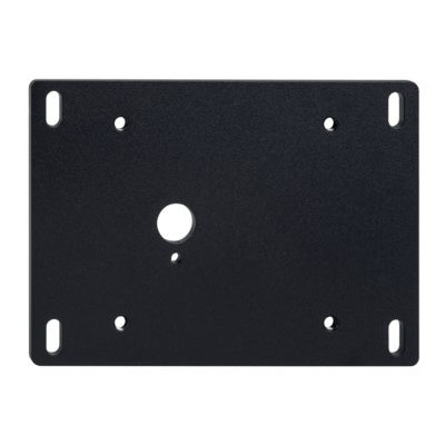
101214126 MP-AZ/AZM201/BDF200-AZ/AZM201-B30
- Montageplaat voor een snelle en eenvoudige installatie
- Metaal, gemoffeld
- Geschikt voor rechts- en linksdraaiende deuren
101185694 MP-AZ/AZM201-P20
- Montageplaat voor een snelle en eenvoudige installatie
- Metaal, gemoffeld
- Geschikt voor rechts- en linksdraaiende deuren
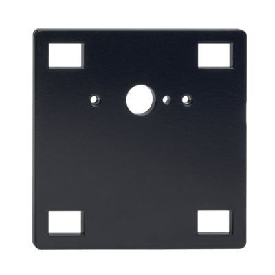
101194224 MP-AZ/AZM201-P1
- Montageplaat voor een snelle en eenvoudige installatie
- Metaal, gemoffeld
- Geschikt voor rechts- en linksdraaiende deuren
101194218 MP-AZ/AZM201-B30
- Montageplaat voor een snelle en eenvoudige installatie
- Metaal, gemoffeld
- Geschikt voor rechts- en linksdraaiende deuren
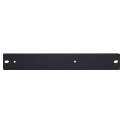
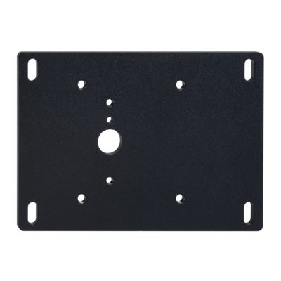
101188600 MP-AZ/AZM201
- Montageplaat voor een snelle en eenvoudige installatie
- Metaal, gemoffeld
Inhoudsopgave
- 1 Over dit document
- 1.1 Functie
- 1.2 Doelgroep van de bedieningshandleiding: gemachtigd personeel
- 1.3 Gebruikte symbolen
- 1.4 Correct gebruik
- 1.5 Algemene veiligheidsinstructies
- 2 Productbeschrijving
- 2.1 Bestelsleutel
- 2.2 Speciale versies
- 2.3 Bestemming en gebruik
- 2.4 Waarschuwing voor foutief gebruik
- 2.5 Uitsluiting van aansprakelijkheid
- 2.6 Technische gegevens
- 3 Montage
- 3.1 Algemene montage-instructies
- 3.2 Afmetingen
- 4 Elektrische aansluiting
- 4.1 Algemene opmerkingen betreffende de elektrische aansluiting
- 4.3 Seriële diagnose -SD
- 4.4 Schakelvoorbeelden voor de serieschakeling
- 4.5 Aansluitconfiguratie en toebehoren aansluitstekker
- 5 Bediensleutel aanleren / bediensleuteldetectie
- 6 Werkprincipes en diagnosefuncties
- 6.1 Aansturing van de magneet
- 6.2 Werkingsprincipe van de veiligheidsuitgangen:
- 6.3 Diagnose-LED's
- 6.4 Veiligheidsvergrendeling met conventionele diagnose-uitgang
- 6.5 Veiligheidsvergrendeling met seriële diagnosefunctie SD
- 7 Gebruik en onderhoud
- 8 Demontage en afvalverwijdering
- 8.1 Demontage
- 8.2 Afvalverwijdering
- 9 Bijlage – Speciale versies
1 Over dit document
1.1 Functie
1.2 Doelgroep van de bedieningshandleiding: gemachtigd personeel
Alle activiteiten die in deze bedieningshandleiding beschreven worden, mogen uitsluitend door gekwalificeerd vakpersoneel, dat hiertoe gemachtigd is door de eigenaar van de machine of installatie, uitgevoerd worden.
Zorg ervoor dat u de bedieningshandleiding gelezen heeft en begrijpt voordat u het component installeert en in werking stelt.
Bij de keuze en inbouw van de componenten en bij hun integratie in de besturing moet de machinebouwer rekening houden met de normbepalingen en hun eisen.
Alle vermeldingen zijn vrijblijvend en zonder enige contractuele verbintenis. Technische wijzigingen voorbehouden.
1.3 Gebruikte symbolen
- Informatie, tip, opmerking: Dit symbool markeert nuttige extra informatie.
- Voorzichtig: Het niet-naleven van deze waarschuwing kan tot storingen, een foutieve werking of defecten leiden.
Waarschuwing: Het niet-naleven van deze waarschuwing kan tot lichamelijke verwondingen en/of materiële schade aan de machine tot gevolg hebben.
1.4 Correct gebruik
Het productassortiment van Schmersal is niet bedoeld voor particuliere consumenten.
De hier beschreven producten werden ontwikkeld om veiligheidsrelevante functies uit te voeren als onderdeel van een volledige machine of installatie. De bouwer van een machine of installatie is verantwoordelijk voor de correcte werking van het geheel.
De veiligheidscomponent mag uitsluitend voor de door de fabrikant toegestane toepassingen en doeleinden gebruikt worden. Gedetailleerde informatie over het toepassingsgebied vindt u in het hoofdstuk "Productbeschrijving".
1.5 Algemene veiligheidsinstructies
De gebruiker moet de veiligheidsinstructies van deze bedieningshandleiding alsmede de nationale installatienormen en de geldende veiligheids- en ongevallenpreventievoorschriften in acht nemen.
- Aanvullende technische informatie vindt u in de Schmersal catalogi of in de online catalogus: products.schmersal.com.
2 Productbeschrijving
2.1 Bestelsleutel
| Typebenaming van het product: AZM201(1)-(2)-(3)-T-(4)-(5) |
| (1) | |
| Z | Bewaking van de veiligheidsvergrendeling |
| B | Bewaking van de bediensleutel |
| (2) | |
| zonder | Standaard codering |
| I1 | Individuele codering |
| I2 | Individuele codering, meerdere keren aanleerbaar |
| (3) | |
| SK | Schroefaansluitklemmen |
| CC | Veeraansluitklemmen |
| ST2 | Inbouwstekker M12, 8-polig |
| (4) | |
| 1P2PW | 1 diagnose-uitgang, met p-schakeling en >2 veiligheidsuitgangen, met p-schakeling>(gecombineerd diagnosesignaal: beschermvoorziening gesloten en vergrendeling vergrendeld) |
| SD2P | seriële diagnose-uitgang en 2 veiligheidsuitgangen met p-schakeling |
| (5) | |
| zonder | ruststroomprincipe |
| A | arbeidsstroomprincipe |
| Bedieningssleutel | Geschikt voor: |
|---|---|
| AZ/AZM201-B1-... | Verschuifbare beschermvoorzieningen |
| AZ/AZM201-B30-... | Draaibare beschermvoorzieningen |
| AZ/AZM201-B40-... | Deuren met aanslag met overlappende vouw. |
2.2 Speciale versies
Voor speciale versies die niet in de typesleutel vermeld worden, gelden de vermeldingen hiervoor en hierna, voor zover zij overeenstemmen met de serieversies.
- Speciale of van de norm afwijkende informatie over speciale uitvoeringen vindt u in het afsluitende hoofdstuk "Appendix – Speciale uitvoeringen".
2.3 Bestemming en gebruik
De contactloos werkende elektronische veiligheidsschakelcomponent is ontworpen voor gebruik in veiligheidscircuits en dient voor de positiebewaking en vergrendeling van bewegende beschermvoorzieningen.
- De veiligheidsschakelcomponenten zijn volgens EN ISO 14119 als type 4 vergrendelvoorzieningen geclassificeerd. Uitvoeringen met individuele codering zijn als hoog gecodeerd ingedeeld.
De verschillende varianten van de component kunnen als veiligheidsschakelaar met vergrendelfunctie of als veiligheidsvergrendeling gebruikt worden.
- Wanneer op basis van de risicoanalyse een veilig bewaakte veiligheidsvergrendeling vereist is, moet een variant met bewaking van de vergrendeling, in de bestelsleutel gekenmerkt door het symbool >, worden gebruikt.
Bij de variant met bewaking van de bediensleutel (B) gaat het om een veiligheidsschakelaar met vergrendelfunctie voor de bescherming van het proces.
De veiligheidsfunctie bestaat uit het veilig uitschakelen van de veiligheidsuitgangen bij het ontgrendelen of het openen van de beschermvoorziening en het behouden van de uitgeschakelde toestand van de veiligheidsuitgangen zolang de beschermvoorziening geopend of ontgrendeld blijft.
- Omdat bij spanningsuitval of het bedienen van de hoofdschakelaar de beschermvoorziening onmiddellijk geopend kan worden, mogen de veiligheidsvergrendelingen met arbeidsstroomprincipe alleen in uitzonderlijke gevallen na precieze inschatting van het ongevallenrisico gebruikt worden.
Serieschakeling
Het toepassen van een serieschakeling is mogelijk. Bij een serieschakeling blijft de risicotijd ongewijzigd en verhoogt de reactietijd met de som van de in de technische gegevens opgegeven reactietijd van de ingangen per bijkomend toestel. Het aantal componenten wordt uitsluitend beperkt door de kabelverliezen en door de externe kabelbescherming, volgens de technische gegevens. Een serieschakeling van toestellen met seriële diagnosefunctie is mogelijk tot een maximum van 31 componenten.
- De gebruiker moet het veiligheidscircuit evalueren, ontwerpen en opbouwen volgens de van toepassing zijnde normen en afhankelijk van het vereiste veiligheidsniveau. Als meerdere veiligheidssensoren deelnemen aan eenzelfde veiligheidsfunctie, moeten de PFH waarden van de individuele componenten opgeteld worden.
- Het volledige concept van de besturing, waarin de veiligheidscomponent geïntegreerd wordt, moet gevalideerd worden volgens de relevante normen.
2.4 Waarschuwing voor foutief gebruik
- Bij ondeskundig of niet-correct gebruik of manipulaties kunnen bij gebruik van de component mogelijke gevaren voor personen of schade aan machine- of installatieonderdelen niet uitgesloten worden. Bij naleving van de veiligheidsinstructies en de instructies voor montage, inwerkingstelling, bediening en onderhoud zijn geen restrisico's bekend.
2.5 Uitsluiting van aansprakelijkheid
Wij zijn niet aansprakelijk voor schade en bedrijfsstoringen die voortvloeien uit montagefouten of het niet naleven van deze bedieningshandleiding. Voor schade die ontstaat vanwege het gebruik van reserveonderdelen of toebehoren, die niet door de fabrikant toegelaten zijn, is iedere vorm van aansprakelijkheid van de fabrikant uitgesloten.
Om veiligheidsredenen is het eigenhandig herstellen, ombouwen of veranderen van het component uitdrukkelijk verboden. Iedere eigenmachtig uitgevoerde reparatie, ombouw of verandering is uit veiligheidsoogpunt niet toegestaan, en ontslaat in voorkomend geval de fabrikant van elke aansprakelijkheid en/of daaruit voortvloeiende schade.
2.6 Technische gegevens
Certificeringen - Voorschriften
|
TÜV cULus FCC IC UKCA ANATEL |
Algemene gegevens
| Voorschriften |
EN ISO 13849-1 EN ISO 14119 EN IEC 60947-5-3 EN IEC 61508 |
| algemene informatie |
Universele codering |
| Codeerniveau volgens EN ISO 14119 |
gering |
| Werkingsprincipe |
RFID |
| Frequentieband RFID |
125 kHz |
| Zendvermogen RFID, maximum |
-6 dBm |
| Materiaal van de behuizing |
Kunststof, glasvezelversterkte thermoplast |
| Risicotijd, maximum |
200 ms |
Reactietijd van de veiligheidsuitgangen in geval van uitschakeling door de actuator, maximaal |
100 ms |
Reactietijd van de veiligheidsuitgangen bij uitschakeling door de veiligheidsingangen, maximaal |
1,5 ms |
| Brutogewicht |
566 g |
Algemene gegevens - Eigenschappen
| ruststroomprincipe |
Ja |
| Bewaking van de vergrendeling |
Ja |
| hulpontgrendeling |
Ja |
| Kortsluitdetectie mogelijk |
Ja |
| Dwarssluitingsherkenning |
Ja |
| Serieschakeling |
Ja |
| Veiligheidsfuncties |
Ja |
| Geïntegreerde weergave, status |
Ja |
| Aantal veiligheidscontacten |
2 |
Classificatie
| Voorschriften |
EN ISO 13849-1 EN IEC 61508 |
Veiligheidsclassificatie - Arrêteerfunctie
| Performance Level, tot |
e |
| Sturingscategorie |
4 |
| PFH waarde |
1,90 x 10⁻⁹ /h |
| PFD waarde |
1,60 x 10⁻⁴ |
| Safety Integrity Level (SIL), geschikt voor toepassingen in |
3 |
| Gebruiksduur |
20 Jaar (Jaren) |
Veiligheidsclassificatie - Vergrendelfunctie
| Performance Level, tot |
d |
| Sturingscategorie |
2 |
| PFH waarde |
1,00 x 10⁻⁸ /h |
| PFD waarde |
8,90 x 10⁻⁴ |
| Safety Integrity Level (SIL), geschikt voor toepassingen in |
2 |
| Gebruiksduur |
20 Jaar (Jaren) |
Mechanische gegevens
| Mechanische levensduurduur, minimum |
1.000.000 schakelingen |
| Blokkeerkracht FZh volgens IOS14119 |
2.000 N |
| Opmerking (blokkeerkracht FZh) |
1,000 N when used with the AZ/AZM201-B30 actuator, for indoor use. |
| Blokkeerkracht Fmax, maximum |
2.600 N |
| Opmerking (blokkeerkracht Fmax) |
1.300 N in Verbindung mit einem Betätiger AZ/AZM201-B30 für Innenanbau. |
| Arrêteerkracht |
30 N |
| Max. bedieningssnelheid |
0,2 m/s |
| Uitvoering van de bevestigingsschroeven |
2x M6 |
| Aandraaimoment van de bevestigingsschroeven, maximum |
8 Nm |
| Aandraaimoment voor de bevestigingsschroeven van het toesteldeksel, minimum |
0,7 Nm |
| Aandraaimoment voor de bevestigingsschroeven van het toesteldeksel, maximum |
1 Nm |
| Opmerking |
Torx T10 |
Mechanische gegevens - Aansluittechniek
| Lengte van de sensorketting, maximum |
200 m |
| Opmerking (Lengte van de sensorketting) |
Cable length and cross-section change the voltage drop dependiing on the output current |
| Opmerking (Serieschakeling) |
Unlimited number of devices, oberserve external line fusing, max. 31 devices in case of serial diagnostic SD |
| Kabelingang |
1 x M20 |
| aansluitwijze |
Veerklemaansluiting |
| Draaddoorsnede, minimum |
0,25 mm² |
| Kabeldoorsnede, maximum |
1,5 mm² |
| Opmerking |
Alle specificaties inclusief adereindhulzen. |
| Aderdoorsnede, minimum |
23 AWG |
| Aderdoorsnede, maximum |
15 AWG |
| Toegelaten kabeltype |
solid single-wire solid multi-wire flexible |
Mechanische gegevens - Afmetingen
| Lengte van de sensor |
50 mm |
| Breedte van de sensor |
40 mm |
| Hoogte van de sensor |
220 mm |
Omgevingsvoorwaarden
| Afdichtingsgraad |
IP66 IP67 |
| Omgevingstemperatuur |
-25 ... +60 °C |
| Opslag- en transporttemperatuur |
-25 ... +85 °C |
| Relatieve vochtigheid, maximum |
93 % |
| Opmerking (relatieve vochtigheid) |
niet-condenserend geen berijping |
| Trillingsvastheid |
10 … 150 Hz, Amplitude 0,35 mm |
| schokbestendig |
30 g / 11 ms |
| Beschermklasse |
III |
| Toegelaten opstelhoogte boven NN, maximum |
2.000 m |
Omgevingsvoorwaarden - Isolatieparameters
| Nominale isolatiespanning Ui |
32 VDC |
| Nominale impulsspanningsvastheid Uimp |
0,8 kV |
| Overspanningscategorie |
III |
| Vervuilingsgraad |
3 |
Elektrische gegevens
| Bedrijfsspanning |
24 VDC -15 % / +10 % |
| Nullaststroom I0, typisch |
50 mA |
| Stroomverbruik bij magneet AAN, gemiddelde waarde |
200 mA |
| Stroomverbruik bij magneet AAN, piekwaarde |
700 mA / 100 ms |
| Nominale bedrijfsspanning |
24 VDC |
| Nominale bedrijfsstroom |
1.200 mA |
| Voorwaardelijke nominale kortsluitstroom |
100 A |
| Externe kabelbeveiliging en toestelzekering |
4A gG |
| Tijd voor operationeel, maximum |
4.000 ms |
| Schakelfrequentie, maximum |
1 Hz |
Elektrische gegevens - magneetaansturing IN
| Benaming, magneetaansturing |
IN |
| Schakeldrempels |
-3 V … 5 V (Low) 15 V … 30 V (High) |
| Stroomverbruik bij 24 V |
10 mA |
| Inschakelduur magneet |
100 % |
| Testimpulsduur, maximum |
5 ms |
| Testimpulsinterval, minimum |
40 ms |
| Classificatie ZVEI CB24I, daling |
C0 |
| Classificatie ZVEI CB24I, bron |
C1 C2 C3 |
Elektrische gegevens - Veilige analoge ingangen
| Benaming, veiligheidsingangen |
X1 en X2 |
| Schakeldrempels |
−3 V … 5 V (Low) 15 V … 30 V (High) |
| Stroomverbruik bij 24 V |
5 mA |
| Testimpulsduur, maximum |
1 ms |
| Testimpulsinterval, minimum |
100 ms |
| Classificatie ZVEI CB24I, daling |
C1 |
| Classificatie ZVEI CB24I, bron |
C1 C2 C3 |
Elektrische gegevens - Veilige digitale uitgangen
| Benaming, veiligheidsuitgangen |
Y1 en Y2 |
| Nominale bedrijfsstroom (veiligheidsuitgangen) |
250 mA |
| Uitvoering van de schakelelementen |
kortsluitvast, p-schakelend |
| Spanningsval Ud, maximum |
2 V |
| Lekstroom Ir, maximum |
0,5 mA |
| Spanning, gebruikscategorie DC-13 |
24 VDC |
| Stroom, gebruikscategorie DC-13 |
0,25 A |
| Testimpulsinterval, typisch |
1000 ms |
| Testimpulsduur, maximum |
0,5 ms |
| Classificatie ZVEI CB24I, bron |
C2 |
| Classificatie ZVEI CB24I, daling |
C1 C2 |
Elektrische gegevens - Diagnose-uitgang
| Benaming, Diagnose-uitgangen |
OUT |
| Nominale bedrijfsstroom |
50 mA |
| Uitvoering van de schakelelementen |
kortsluitvast, p-schakelend |
| Spanningsval Ud, maximum |
4 V |
| Spanning, gebruikscategorie DC-13 |
24 VDC |
| Stroom, gebruikscategorie DC-13 |
0,05 A |
Statusindicatie
| Opmerking (LED-statusindicatie) |
Bedrijfstoestand: gele LED Fout / functiestoring: rode LED Voedingsspanning UB: groene LED |
Opmerkingen met betrekking tot de veiligheidsclassificatie
- De veiligheidsclassificatie van de arrêteerfunctie is uitsluitend geldig voor standaardtoestellen met bewaakte arrêteerfunctie AZM201Z-...-1P2PW-... (cf. typesleutel). Een veiligheidsclassificatie van de vergrendelfunctie voor toestellen met seriële diagnose "SD2P" is omwille van de niet-veilige vergrendel-/ontgrendelsignalen door de SD-Gateway niet toegelaten.
- Als in een toepassing de veiligheidsvergrendeling met ruststroomprincipe niet kan gebruikt worden, kan voor dit uitzonderingsgeval een veiligheidsvergrendeling met arbeidsstroomprincipe gebruikt worden, mits bijkomende veiligheidsmaatregelen getroffen worden, die voor een gelijkwaardig veiligheidsniveau zorgen.
- De veiligheidsclassificatie van de arrêteerfunctie heeft betrekking op de component veiligheidsvergrendeling AZM binnen de volledige installatie.
De klant moet verdere maatregelen, zoals een veilige aansturing en een veilige kabelplaatsing met het oog op de uitsluiting van fouten voorzien.
Als zich een storing voordoet, waaruit het ontgrendelen van de arrêteerfunctie voortvloeit, wordt dit door de veiligheidsvergrendeling herkend en worden de veiligheidsuitgangen Y1/Y2 veilig uitgeschakeld. Door het optreden van een dergelijke storing zou de veiligheidsdeur onmiddellijk en eenmalig geopend kunnen worden voordat de veilige toestand van de machine bereikt wordt. Het systeemgedrag van categorie 2 laat toe, dat tussen de tests het optreden van een storing tot het verlies van de veiligheidsfunctie kan leiden en het verlies van de veiligheidsfunctie door de test herkend wordt.
- De aansturing van de veiligheidsvergrendeling moet extern met de OSSD vrijgave vergeleken worden; Als zich hier een uitschakeling door een ongebruikelijke ontgrendeling voordoet, wordt dit door de externe diagnose gedekt. Als zich hier een uitschakeling door een ongebruikelijke ontgrendeling voordoet, wordt dit door de externe diagnose gedekt.
UL-opmerking
Alleen geïsoleerde spanningstoevoer gebruiken. Uitsluitend bedoeld voor gebruik in toepassingen, die voldoen aan de vereisten van de VS-norm NFPA 79. Adapters voor de veldbedrading zijn verkrijgbaar bij de fabrikant. Informatie van de fabrikant in acht nemen.
FCC/IC - Opmerking
Dit toestel is conform aan Deel 15 van de FCC-bepalingen en bevat licentievrije zenders/ontvangers die conform zijn aan de licentievrije RSS-norm(en) van de ISED (Innovation, Science and Economic Development) Canada.
De werking is afhankelijk van de volgende twee voorwaarden:
(1) Dit toestel mag geen schadelijke stoorsignalen veroorzaken, en
(2) Dit toestel moet stoorsignalen kunnen tolereren. Hiertoe behoren ook stoorsignalen die tot een ongewenste werking van het toestel kunnen leiden.
Dit toestel leeft bij gebruik op een minimumafstand van 100 mm de grenswaarden voor het stimuleren van de zenuwen (ISED SPR-002) na. Wijzigingen of aanpassingen die niet uitdrukkelijk zijn goedgekeurd door K.A. Schmersal GmbH & Co. KG, kunnen ertoe leiden dat de gebruiker de bevoegdheid voor het gebruik van het apparaat verliest.
De in dit toestel geïntegreerde, licentievrije zender/ontvanger vervult de voor licentievrije radioapparatuur geldende eisen van de "Radio Standards Specification" van de instantie Innovation, Science and Economic Development Canada (ISED). Het gebruik is onder beide volgende voorwaarden toegelaten:
(1) het toestel mag geen storingen genereren.
(2) het toestel moet bestand zijn tegen ontvangen radio-interferentie, ook als deze zijn werking kan beïnvloeden.
Dit toestel voldoet aan de eisen met betrekking tot de blootstellingsgrenswaarden voor stimulering van de zenuwen (ISED CNR-102) bij processen met een minimumafstand van 100 mm.
Wijzigingen of verbouwingen waarvoor K.A. Schmersal GmbH & Co. KG niet uitdrukkelijk toestemming gegeven heeft, kunnen ertoe leiden dat de gebruiker de vergunning voor het gebruik van het toestel verliest.
| 20941-22-14519 | Este equipamento nao tem direito àprotecao contra interferência prejudicial e nao pode causar interferencia em sistemas devidamente autorizados. Para maiores informacores consultar: www.gov.br/anatel |
3 Montage
3.1 Algemene montage-instructies
- Neem ook de opmerkingen van de normen ISO 12100, ISO 14119 en ISO 14120.
De veiligheidsschakelaar met vergrendelfunctie en de bediensleutel zijn voorzien van telkens twee bevestigingsgaten voor M6 schroeven met onderlegring (onderlegringen inbegrepen in de levering). De behuizing van de component mag niet als aanslag gebruikt worden. De plaats van montage is willekeurig. Het binnendringen van vuil in de gebruikte openingen moet echter vermeden worden. De niet-gebruikte opening van de bediensleutel moet met de stofkap (inbegrepen in de levering) afgedicht worden.
Minimumafstand tussen twee veiligheidsschakelcomponenten
of andere systemen met dezelfde frequentie (125 kHz): 100 mm.

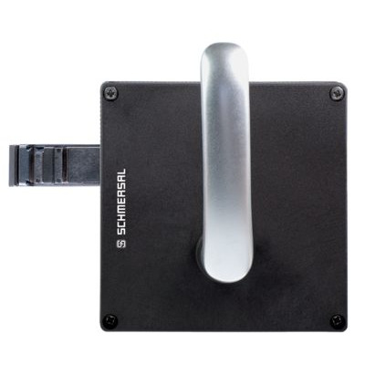
Montage van de bediensleutels
Zie bedieningshandleiding van de bediensleutel in kwestie
- De bediensleutels moeten via geschikte maatregelen (gebruik van eenwegschroeven, lijmen, uitboren van de schroefkoppen, borgen met pennen) onlosmakelijk aan de beschermvoorziening bevestigd worden en tegen verschuiven beveiligd worden.
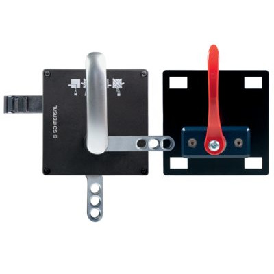
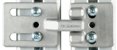
Hulpontgrendeling
Voor het opstellen van de machine kan de veiligheidsvergrendeling spanningsloos ontgrendeld worden. Na het openen van de kunststofklep "A" (zie afbeelding "Afmetingen"), wordt de blokkeerpen in ontgrendelpositie gebracht door de driekantsleutel in wijzerszin te draaien. De normale functie wordt pas hersteld nadat de driekantsleutel terug in zijn uitgangspositie gedraaid is.
- Niet over het blokkeerpunt heen draaien, maximaal aandraaimoment 1,3 Nm.
Na de inwerkingstelling moet de hulpontgrendeling met de kunststofklep "A" afgesloten en met het meegeleverde zegel verzegeld worden.
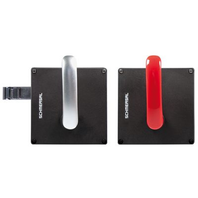
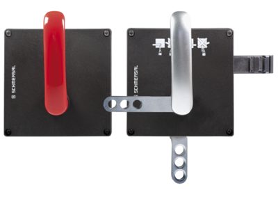
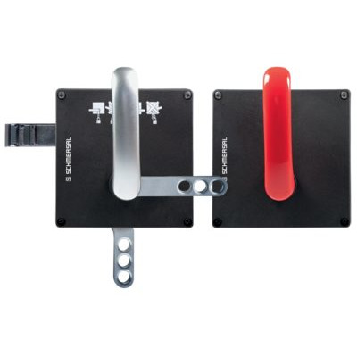
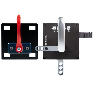
| Component gebruiksklaar | Component niet gebruiksklaar |
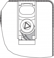 | 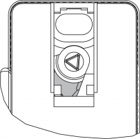 |
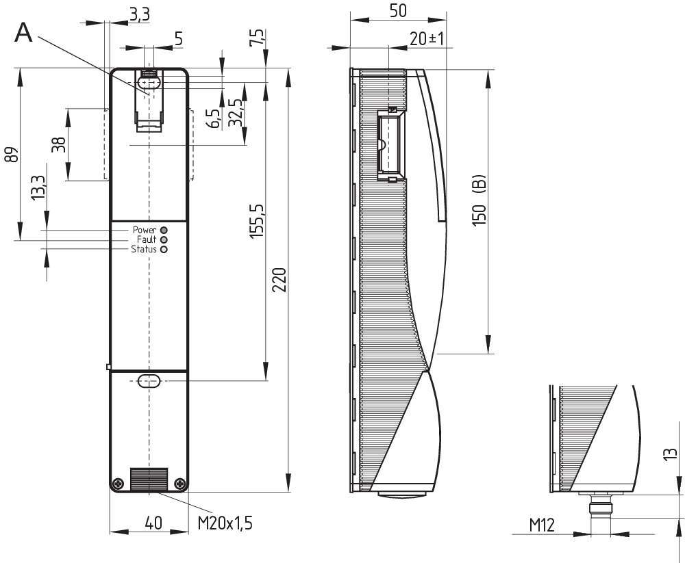
3.2 Afmetingen
Alle maten in mm.
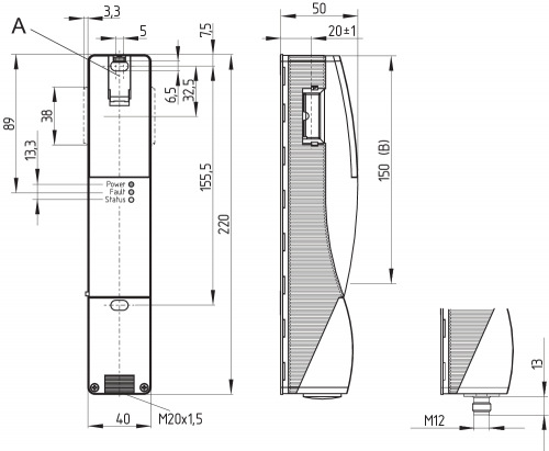
Legende
A: Hulpontgrendeling achter klepje
B: actief RFID-bereik
- Metalen onderdelen en magneetvelden in het zijdelingse RFID-bereik van de veiligheidsschakelcomponent en de bediensleutel kunnen de schakelafstand beïnvloeden of de werking verstoren.
De ombouwkit dient voor de latere functie-uitbreiding van de veiligheidsvergrendeling.
| Benaming | Bestelnummer | |
|---|---|---|
| Noodontgrendeling | RF-AZM200-N | 103003543 |
| Paniekontgrendeling | RF-AZM200-T | 103004966 |
4 Elektrische aansluiting
4.1 Algemene opmerkingen betreffende de elektrische aansluiting
- De elektrische aansluiting mag uitsluitend in spanningsloze toestand door gemachtigd en gekwalificeerd personeel uitgevoerd worden.
De voeding moet worden beschermd tegen permanente overspanning. Daarom moeten gestabiliseerde voedingen volgens EN 60204-1 gebruikt worden.
De vereiste elektrische kabelbescherming moet in de installatie worden voorzien.
De veiligheidsuitgangen kunnen rechtstreeks opgenomen worden in het veiligheidscircuit van de besturing.
Eisen voor de navolgend geschakelde veiligheidsmodule:
Tweekanalige veiligheidsingang, geschikt voor 2 p-schakelende halfgeleideruitgangen
- Configuratie veiligheidsbesturing
Bij aansluiting van de veiligheidsschakelcomponent aan elektronische veiligheidsmodules raden wij aan, een tijdsvertraging van minstens 100 ms in te stellen. De veiligheidsingangen van de veiligheidsmodule moeten een testimpuls van ca.1 ms kunnen maskeren. De veiligheidsmodule moet niet met een dwarssluitdetectie uitgerust zijn; een eventueel aanwezige dwarssluitdetectie moet uitgeschakeld worden.
- Meer informatie voor het kiezen van geschikte veiligheidsmodules vindt u in de Schmersal catalogi of in de online catalogus: products.schmersal.com.
De kabelinvoer gebeurt via een metrische wartel M 20. Deze moet door de gebruiker passend voor de gebruikte kabel gedimensioneerd worden. De gebruikte kabelwartels moeten over een trekontlasting en een geschikte IP beschermgraad beschikken.
Lengte x van de kabel
- aan schroefklemmen (SK): 8 mm
- aan veeraansluitklemmen (CC) van het type s, r of f: 7,5 mm

4.3 Seriële diagnose -SD
- De gemonteerde brug 24V, X1, X2 is inbegrepen in de levering van ...-1P2PW en ...-SD2P.
- Bij het bekabelen van SD componenten moet rekening worden gehouden met de spanningsval op de kabels en de stroombelastbaarheid van de individuele componenten.
- Accessoires voor de serieschakeling
Voor een comfortabele bekabeling en serieschakeling van SD componenten zijn de SD-verdelers PFB-SD-4M12-SD (variant in gesloten behuizing voor gebruik ter plaatse) en PDM-SD-4CC-SD (variant voor installatie op DIN rail in de schakelkast) en een uitgebreid gamma accessoires verkrijgbaar. Gedetailleerde informatie vindt u op het Internet onder products.schmersal.com.
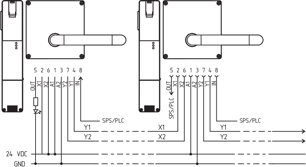
4.4 Schakelvoorbeelden voor de serieschakeling
Het toepassen van een serieschakeling is mogelijk. Bij een serieschakeling blijft de risicotijd ongewijzigd en verhoogt de reactietijd met de som van de in de technische gegevens opgegeven reactietijd van de ingangen per bijkomend toestel. Het aantal componenten wordt uitsluitend beperkt door de kabelverliezen en door de externe kabelbescherming, volgens de technische gegevens. Een serieschakeling van AZM201...-SD met seriële diagnosefunctie is mogelijk tot een maximum van 31 componenten.
De getoonde toepassingsvoorbeelden zijn voorstellen. De gebruiker moet echter de schakeling en de geschiktheid van het product voor de specifieke toepassing controleren.
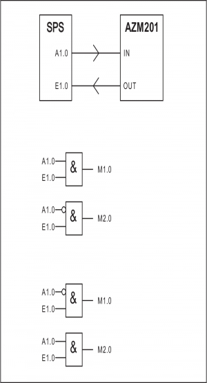
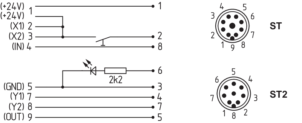
Aansluitvoorbeeld 1: Serieschakeling van de AZM201 met conventionele diagnose-uitgang
Bij de serieschakeling moet de brug 24V-X1-X2 tot aan de laatste component uit alle componenten verwijderd worden. De spanning wordt in de beide veiligheidsingangen van de laatste veiligheidscomponent van de ketting (gezien vanaf de veiligheidsmodule) gevoed. De veiligheidsuitgangen van de eerste veiligheidscomponent worden op de veiligheidsmodule aangesloten.
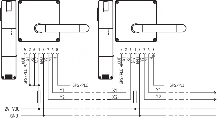
Y1 en Y2 = veiligheidsuitgangen → veiligheidsmodule
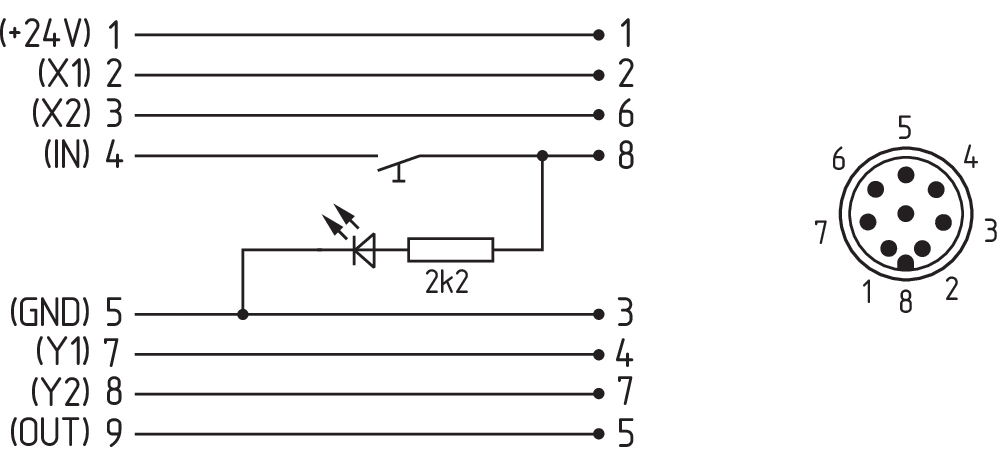
Aansluitvoorbeeld 2: Serieschakeling AZM201 met seriële diagnosefunctie (max. 31 componenten in serie)
Bij componenten met seriële diagnosefunctie (bestelindex -SD) worden de seriële aansluitingen in serie geschakeld en voor evaluatie op een SD-Gateway aangesloten. De veiligheidsuitgangen van de eerste veiligheidscomponent worden op de veiligheidsmodule aangesloten. De seriële Diagnose Gateway wordt met de seriële diagnose-ingang van de eerste veiligheidscomponent verbonden.

Y1 en Y2 = veiligheidsuitgangen → veiligheidsmodule
SD-IN → Gateway → Fieldbus
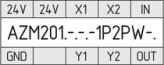
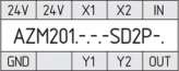
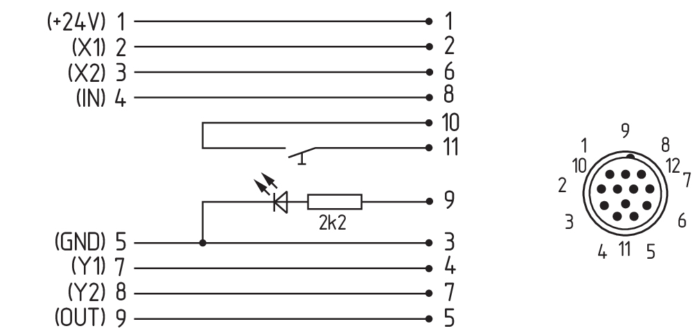
4.5 Aansluitconfiguratie en toebehoren aansluitstekker
| Functie van het veiligheidscomponent | Pinconfiguratie van de inbouwstekker ST2 M12, 8-polig | Configuratie van de afneembare klemlijsten | Kleurencodesvan de Schmersal stekkers volgens DIN 47100 | Mogelijke kleurencode van andere courant verkrijgbare aansluitstekkers Kleurencode van andere courant verkrijgbare aansluitstekkers volgens EN 60947-5-2 | ||
|---|---|---|---|---|---|---|
| met conventionele diagnose-uitgang | met seriële diagnose |  | ||||
| 24V | Ue | 1 | 1 | WH | BN | |
| X1 | Veiligheidsingang 1 | 2 | 2 | BN | WH | |
| GND | GND | 3 | 5 | GN | BU | |
| Y1 | Veiligheidsuitgang 1 | 4 | 7 | YE | BK | |
| OUT | Diagnose-uitgang | SD uitgang | 5 | 9 | GY | GY |
| X2 | Veiligheidsingang 2 | 6 | 3 | PK | PK | |
| Y2 | Veiligheidsuitgang 2 | 7 | 8 | BU | VT | |
| IN | Magneetaansturing | SD ingang | 8 | 4 | RD | OF |
| zonder functie | - | 6 | ||||
Afwijkende aansluitingsbezetting bij gebruik van de Y-verdeler CSS-Y-8P voor aansluiting op de SD-Gateway.
| Signaal | Pin | Stekker (2) | Aderkleuren van de | |||
|---|---|---|---|---|---|---|
| SCHMERSAL- kabel | kabel volgens EN 60947-5-2 | kabel volgens DIN 47100 | ||||
| A1 | 1 | Ue | BN | BN | WH |  |
| A1 | 2 | Ue | WH | WH | BN | |
| A2 | 3 | GND | BU | BU | GN | |
| A2 | 4 | GND | BK | BK | YE | |
| Y1 | 5 | Veiligheidsuitgang 1 | GY | GY | GY | |
| Y2 | 6 | Veiligheidsuitgang 2 | VT | PK | PK | |
| IN | 7 | SD ingang | RD | VT | BU | |
| OUT | 8 | SD uitgang | PK | OF | RD | |
| Aanzicht klemlijsten voor bestelindex -SK of CC | Aanzicht uitvoering met afneembare klemlijsten | |
|---|---|---|
 |  |  |
| Aansluitkabels met koppeling (female) IP67 / IP69, M12, 8-polig - 8 x 0,25 mm² volgens DIN 47100 | |
|---|---|
| Kabellengte | Bestelnummer |
| 2,5 m | 103011415 |
| 5,0 m | 103007358 |
| 10,0 m | 103007359 |
| 15,0 m | 103011414 |
5 Bediensleutel aanleren / bediensleuteldetectie
Veiligheidsvergrendelingen met standaardcodering zijn bij levering klaar voor gebruik.
Individueel gecodeerde veiligheidsvergrendelingen en bediensleutels worden volgens de onderstaande procedures aan elkaar aangeleerd:
- Veiligheidsvergrendeling uitschakelen en opnieuw onder spanning zetten.
- Bediensleutel in het detectiebereik brengen. De leerprocedure wordt aan de veiligheidsvergrendeling gesignaleerd, de groene LED is uitgeschakeld, de rode LED brandt, de gele LED knippert (1 Hz).
- Na 10 seconden geven korte knipperimpulsen (3 Hz) aan dat de bedrijfsspanning van de veiligheidsschakelaar uitgeschakeld moet worden. (Wordt de spanning niet binnen 5 minuten uitgeschakeld, dan breekt de veiligheidsvergrendeling de leerprocedure af en knippert hij 5 maal rood om een foutieve bediensleutel te signaleren.)
- Zodra de bedrijfsspanning opnieuw ingeschakeld wordt, moet de bediensleutel opnieuw gedetecteerd worden om de geleerde bediensleutelcode te activeren. De geactiveerde code wordt op die manier definitief opgeslagen.
Bij besteloptie -I1 is de uitgevoerde toewijzing van veiligheidsschakelcomponent en bediensleutel onomkeerbaar.
Bij besteloptie -I2 kan de procedure voor het aanleren van een nieuwe bediensleutel onbegrensd herhaald worden. Bij het aanleren van een nieuwe bediensleutel wordt de op dat ogenblik actieve code ongeldig. Daarnaast garandeert een vrijgaveblokkering van 10 minuten een verhoogde beveiliging tegen manipulatie. De groene LED knippert tot de tijd van de vrijgaveblokkering verstreken is en de nieuwe bediensleutel gedetecteerd is. In geval van een spanningsonderbreking tijdens het verstrijken van de tijd, begint de manipulatiebeveiligingstijd van 10 minuten vanaf nul opnieuw te lopen.
6 Werkprincipes en diagnosefuncties
6.1 Aansturing van de magneet
Bij de ruststroomversie van de AZM 201 is de veiligheidsvergrendeling ontgrendeld bij een bedrijfsmatige "set" van het IN signaal (= 24V). Bij de arbeidsstroomversie van de AZM 201 is de veiligheidsvergrendeling vergrendeld bij een bedrijfsmatige "set" van het IN signaal (= 24V).
6.2 Werkingsprincipe van de veiligheidsuitgangen:
Bij de standaardversie AZM 201 leidt het ontgrendelen van de veiligheidsvergrendeling tot de uitschakeling van de veiligheidsuitgangen. Zolang de bediensleutel in de veiligheidsvergrendeling AZM 201 ingevoerd blijft, kan de ontgrendelde beschermvoorziening opnieuw vergrendeld worden; in dat geval worden de veiligheidsuitgangen opnieuw ingeschakeld.
De veiligheidsdeur hoeft daarbij niet geopend te worden.
Bij de B-variante AZM 201B veroorzaakt het openen van de beschermvoorziening
de uitschakeling van de veiligheidsuitgangen.
6.3 Diagnose-LED's
De veiligheidsvergrendeling geeft zijn bedrijfstoestand en storingen weer via een driekleurige LED aan de voorkant van het toestel.
| groen (power) | Voedingsspanning aanwezig |
| geel (status) | bedrijfstoestanden |
| rood (fault) | Fout (zie tabel 2: foutmeldingen / impulscodes rode diagnose-LED) |
6.4 Veiligheidsvergrendeling met conventionele diagnose-uitgang
De kortsluitvaste diagnose-uitgang OUT kan voor centrale visualisatie- of besturingstaken gebruikt worden, bijvoorbeeld in een PLC.
De diagnose-uitgang is geen veiligheidsrelevante uitgang!
Fout
Storingen waardoor de veilige werking van de veiligheidsschakelcomponent niet langer gewaarborgd is (interne storingen), leiden tot de uitschakeling van de veiligheidsuitgangen binnen de risicotijd. Na het elimineren van de fout wordt de foutmelding gereset door het openen en opnieuw sluiten van de bijbehorende veiligheidsdeur.
- Wordt meer dan een fout aan de veiligheidsuitgangen of een dwarssluiting tussen Y1 en Y2 gedetecteerd, dan vergrendelt de veiligheidsvergrendeling automatisch elektronisch.. Fouten kunnen dan niet meer op een normale manier worden gereset. Om deze vergrendeling te resetten, moet de veiligheidsvergrendeling na het opheffen van de foutoorzaken eenmaal van de voedingsspanning gescheiden worden.
Foutwaarschuwing
Een storing die de veilige werking van de veiligheidsschakelcomponent niet onmiddellijk in gevaar brengt (bijv. te hoge omgevingstemperatuur, externe potentiaal aan veiligheidsuitgang, dwarssluiting) leidt tot een vertraagde uitschakeling (zie Tabel 2). Deze signaalcombinatie "diagnose-uitgang uitgeschakeld" en "veiligheidsuitgangen nog altijd ingeschakeld" kan gebruikt worden om de machine op een gecontroleerde manier te stoppen.
Een foutwaarschuwing wordt verwijderd als de fout-oorzaak opgeheven wordt.
Als de foutwaarschuwing 30 minuten actief is, worden ook de veiligheidsuitgangen uitgeschakeld (rode LED knippert, zie Tabel 2).
Gedrag diagnose-uitgang (model ...-1P2PW)
(voorbeeld: ruststroommodel)
Ingangssignaal magneetaansturing

Normale afloop, deur werd vergrendeld
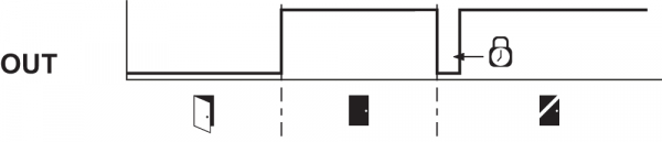
Deur kon niet vergrendeld worden of storing

 | Vergrendelen |  | Ontgrendeling | ||
 | Deur geopend |  | Deur gesloten |  | Vergrendeltijd: 150 ... 250 ms, typisch 200 ms |
 | Deur niet vergrendeld of fout |  | Deur vergrendeld |
Evaluatie diagnose-uitgang (uitvoering ...-1P2PW)
| Tabel 1: Diagnose-informatie van de veiligheidsschakelcomponent | ||||||||
|---|---|---|---|---|---|---|---|---|
| Toestand van het systeem | Magneetaansturing IN | LED | Veiligheidsuitgang Y1, Y2 | Diagnose-uitgang OUT | ||||
| Ruststroom | Arbeidsstroom | groen | rood | geel | AZM201Z | AZM201B | -1P2PW | |
| deur open | 24 V (0 V) | 0 V (24 V) | aan | uit | uit | 0 V | 0 V | 0 V |
| Deur gesloten, bediensleutel ingevoerd | 24 V | 0 V | aan | uit | uit | 0 V | 0 V | 0 V |
| Deur gesloten, bediensleutel ingevoerd, niet vergrendeld | 24 V | 0 V | aan | uit | knippert | 0 V | 24 V | 24 V |
| Deur gesloten, bediensleutel ingevoerd, vergrendeling geblokkeerd | 0 V | 24 V | aan | uit | knippert | 0 V | 24 V | 0 V |
| Deur gesloten, bediensleutel ingevoerd en vergrendeld | 0 V | 24 V | aan | uit | aan | 24 V | 24 V | 24 V |
| Foutwaarschuwing1) Vergrendeling vergrendeld | 0 V | 24 V | aan | knippert2) | aan | 24 V1) | 24 V1) | 0 V |
| Fout | 0 V (24 V) | 24 V (0 V) | aan | knippert2)/uit1) | uit | 0 V | 0 V | 0 V |
| Extra bij uitvoering I1/I2: | ||||||||
| Aanleren bediensleutel gestart | uit | aan | knippert | 0 V | 0 V | 0 V | ||
| Alleen I2: leerproces bediensleutel (vrijgaveblokkering) | knippert | uit | uit | 0 V | 0 V | 0 V | ||
1) na 30 min: uitschakeling wegens fout 2) zie knippercodes | ||||||||
| Tabel 2: Foutmeldingen / Impulscodes rode diagnose-LED | |||
|---|---|---|---|
| Impulscodes | Benaming | autonome uitschakeling na | Foutoorzaak |
| 1 impuls | Fout(waarschuwing) aan uitgang Y1 | 30 min | Fout in uitgangstest of spanning aan uitgang Y1, hoewel de uitgang uitgeschakeld is |
| 2 impulsen | Fout(waarschuwing) aan uitgang Y2 | 30 min | Fout in uitgangstest of spanning aan uitgang Y2, hoewel de uitgang uitgeschakeld is |
| 3 impulsen | Fout(waarschuwing) dwarssluiting | 30 min | Dwarssluiting tussen de uitgangskabels of fout aan de beide uitgangen |
| 4 impulsen | Fout(waarschuwing) temperatuur te hoog | 30 min | De temperatuurmeting toont een te hoge interne temperatuur |
| 5 impulsen | Fout Bediensleutel | 0 min | Foutieve of defecte bediensleutel |
| 6 impulsen | Foutieve bediensleutel | 0 min | Er werd een ongeldige combinatie van bediensleutels gedetecteerd (vergrendelpen gedetecteerd of poging tot manipulatie/frauderen). |
| continu rood signaal | interne fout / fout spanning te hoog of te laag | 0 min | Toestel defect / voedingsspanning buiten specificaties |
6.5 Veiligheidsvergrendeling met seriële diagnosefunctie SD
Veiligheidsvergrendelingen met een kabel voor seriële diagnose bezitten een seriële ingangs- en uitgangskabel in plaats van de conventionele diagnose-uitgang. Bij de serieschakeling van veiligheidsvergrendelingen worden de diagnostische gegevens via de serieschakeling van deze ingangs- en uitgangskabels overgedragen.
Maximaal 31 veiligheidsdvergrendelingen kunnen in serie geschakeld worden. Voor de evaluatie van de seriële diagnose wordt de PROFIBUS Gateway SD-I-DP-V0-2 of de Universal Gateway SD-I-U-... gebruikt. Deze interface voor seriële diagnose wordt als slave geïntegreerd in een bestaand veldbussysteem. De diagnosesignalen kunnen op die manier via een PLC geëvalueerd worden.
De nodige software voor de integratie van de SD Gateway kan via products.schmersal.com gedownload worden.
De responsedata en de diagnosegegevens worden voor iedere veiligheidsvergrendeling in de keten automatisch en permanent in een ingangsbyte van de PLC geschreven. De oproepgegevens voor iedere veiligheidsvergrendeling worden telkens via een uitgangsbyte van de PLC aan de component overgedragen. Als er een communicatiefout tussen de SD-gateway en de veiligheidsvergrendeling optreedt, dan behoudt de veiligheidsvergrendeling haar schakeltoestand.
Fout
Storingen waardoor de veilige werking van de veiligheidsschakelcomponent niet langer gewaarborgd is (interne storingen), leiden tot de uitschakeling van de veiligheidsuitgangen binnen de risicotijd. De fout wordt gereset, als de oorzaak wegvalt en bit 7 van de oproepbyte van 1 in 0 wijzigt of de deur geopend wordt. Storingen aan de veiligheidsuitgangen worden pas na de volgende vrijgave gewist, omdat de foutoplossing niet eerder gedetecteerd kan worden.
- Wordt meer dan een fout aan de veiligheidsuitgangen of een dwarssluiting tussen Y1 en Y2 gedetecteerd, dan vergrendelt de veiligheidsvergrendeling automatisch elektronisch.. Fouten kunnen dan niet meer op een normale manier worden gereset. Om deze vergrendeling te resetten, moet de veiligheidsvergrendeling na het opheffen van de foutoorzaken eenmaal van de voedingsspanning gescheiden worden.
Foutwaarschuwing
Een storing die de veilige werking van de veiligheidsschakelcomponent niet onmiddellijk in gevaar brengt (bijv. te hoge omgevingstemperatuur, externe potentiaal aan veiligheidsuitgang, dwarssluiting) leidt tot een vertraagde uitschakeling. De signaalcombinatie "diagnose-uitgang uitgeschakeld" en "veiligheidsuitgangen nog altijd ingeschakeld" kan worden gebruikt om de machine op een gecontroleerde manier te stoppen.
Bij het verdwijnen van de oorzaak wordt een foutwaarschuwing weer ingetrokken.
Als de foutwaarschuwing 30 minuten actief is, worden ook de veiligheidsuitgangen uitgeschakeld (rode LED knippert).
Diagnose fout (waarschuwing)
Van iedere storing die in de antwoordbyte gemeld wordt, kan uitgebreide foutinformatie uitgelezen worden.
| Tabel 3: I/O gegevens en diagnosegegevens (De beschreven toestand is bereikt als bit = 1) | ||||
|---|---|---|---|---|
| Bitnr. | Commandobyte | Antwoordbyte | Diagnose foutwaarschuwing | Diagnose storing |
| Bit 0 | Magneet in, onafhankelijk van arbeids- of ruststroomprincipe | Veiligheidsuitgang ingeschakeld | Storing uitgang Y1 | Storing uitgang Y1 |
| Bit 1 | --- | Bediensleutel gedetecteerd | Storing uitgang Y2 | Storing uitgang Y2 |
| Bit 2 | --- | Bediensleutel gedetecteerd en vergrendeld | Dwarssluiting | Dwarssluiting |
| Bit 3 | --- | --- | Temperatuur te hoog | Temperatuur te hoog |
| Bit 4 | --- | Toestand ingang X1 en X2 | --- | Foutieve of defecte bediensleutel |
| Bit 5 | --- | Deur gedetecteerd | Interne storing | Interne storing |
| Bit 6 | --- | Foutwaarschuwing 1) | Communicatiefout tussen de veldbus gateway en de veiligheidsvergrendeling | --- |
| Bit 7 | Fout reset | Storing (vrijgavecontact uitgeschakeld) | Te lage bedrijfsspanning | --- |
| 1) na 30 min -> fout | ||||
7 Gebruik en onderhoud
De veiligheidsfunctie van de veiligheidsschakelaar moet getest worden. Bij een correcte installatie en doelmatig gebruik vereist de veiligheidscomponent geen onderhoud. Wij raden een regelmatige visuele inspectie en functietest aan, inclusief de volgende stappen:
- Bevestiging van het veiligheidsschakelapparaat en de bediensleutel controleren.
- Controle van de max. zijdelingse afwijking van bediensleutel en veiligheidsschakelcomponent.
- Intactheid van de kabelaansluitingen.
- Eventuele schade aan de behuizing van de schakelaar.
- Verwijdering van stof en vuil
- Tijdens alle bedrijfsmatige levensfasen van de veiligheidsschakelcomponent moeten constructief en organisatorisch geschikte maatregelen voor de manipulatiebeveiliging of tegen het manipuleren van de veiligheidsvoorziening, bijvoorbeeld door het gebruik van een vervangende bediensleutel, getroffen worden.
- Beschadigde of defecte componenten moeten onmiddellijk vervangen worden.
8 Demontage en afvalverwijdering
8.1 Demontage
De veiligheidsschakelaar mag uitsluitend in spanningsloze toestand gedemonteerd worden.
8.2 Afvalverwijdering
- Het veiligheidscomponent moet op een correcte manier volgens de geldende nationale voorschriften en wetgevingen afgevoerd worden.
9 Bijlage – Speciale versies
Speciale versies -2965-1
| Aansluitkabels met koppeling (female) IP67, M23, 12-polig - 12 x 0,75 mm² | |
|---|---|
| Kabellengte | Bestelnummer |
| 5,0 m | 101208520 |
| 10,0 m | 103007354 |
| 20,0 m | 101214418 |
Speciale versies -2965-2
| Aansluitkabels met koppeling (female) IP67, M23, 8+1-polig - 9 x 0,75 mm² | |
|---|---|
| Kabellengte | Bestelnummer |
| 5,0 m | 101209959 |
| 10,0 m | 101209958 |
| 15,0 m | 103001384 |
| Aansluitkabels met koppeling (female) IP67, M12, 8-polig - 8 x 0,25 mm² | |
|---|---|
| Kabellengte | Bestelnummer |
| 2,5 m | 103011415 |
| 5,0 m | 103007358 |
| 10,0 m | 103007359 |
Speciale versies -2965-3
| Aansluitkabels met koppeling (female) IP67, M12, 8-polig - 8 x 0,25 mm² | |
|---|---|
| Kabellengte | Bestelnummer |
| 2,5 m | 103011415 |
| 5,0 m | 103007358 |
| 10,0 m | 103007359 |
| EU-conformiteitsverklaring |  |
| Original | K.A. Schmersal GmbH & Co. KG Möddinghofe 30 42279 Wuppertal Germany Internet: www.schmersal.com |
| Verklaring: | Hiermee verklaren wij dat de hieronder beschreven producten op grond van hun ontwerp en constructie beantwoorden aan de relevante Europese Richtlijnen. |
| Benaming van de component: | AZM201 |
| Type: | zie bestelsleutel |
| Beschrijving van de component: | Vergrendelvoorziening met elektromagnetische vergrendeling voor veiligheidsfuncties |
| Geharmoniseerde Richtlijnen: | Machinerichtlijn | 2006/42/EG |
| RED-Richtlijn | 2014/53/EU | |
| RoHS-Richtlijn | 2011/65/EU |
| Toegepaste normen: | EN 60947-5-3:2013 ISO 14119:2013 EN 300 330 V2.1.1:2017 EN ISO 13849-1:2015 EN 61508 Deel 1-7:2010 |
| Bevoegde installatie voor de typekeuring: | TÜV Rheinland Industrie Service GmbH Am Grauen Stein, 51105 Köln Kenn Nr.: 0035 |
| EG-Goedkeuringscertificaat: | 01/205U/5608.00/22 |
| Gemachtigde voor het samenstellen van de technische documentatie: | Oliver Wacker Möddinghofe 30 42279 Wuppertal |
| Plaats en datum van opstelling: | Wuppertal, 10. augustus 2022 |
 |
| Rechtsgeldige handtekening Philip Schmersal Directeur |
| UK Declaration of Conformity | |
| Company: | K.A. Schmersal GmbH & Co. KG Möddinghofe 30 42279 Wuppertal Germany Internet: www.schmersal.com |
| Declaration: | We hereby, under sole responsibility, certify that the hereafter described components both in their basic design and construction conform to the relevant statutory requirements, regulations and designated standards of the United Kingdom. |
| Name of the component: | AZM201 |
| Type: | See ordering code |
| Description of the component: | Interlocking device with electromagnetic interlock for safety functions |
| Relevant legislation: | Supply of Machinery (Safety) Regulations | 2008 |
| Radio Equipment Regulations | 2017 | |
| The Restriction of the Use of Certain Hazardous Substances in Electrical and Electronic Equipment Regulations | 2012 |
| Designated standards: | EN 60947-5-3:2013 ISO 14119:2013 EN 300 330 V2.1.1:2017 EN ISO 13849-1:2015 EN 61508 parts 1-7:2010 |
| Approved body for Type Examination: | TÜV Rheinland UK Ltd. 1011 Stratford Road Solihull, B90 4BN ID: 2571 |
| Type examination certificate: | 01/205U/5608.00/22 |
| UK-Importer / Person authorised for the compilation of the technical documentation: | Schmersal UK Ltd. Paul Kenney Unit 1, Sparrowhawk Close Enigma Business Park Malvern, Worcestershire, WR14 1GL |
| Place and date of issue: | Wuppertal, September 28, 2022 |
|
| Authorised signature Philip Schmersal Managing Director |
Schmersal Belgium, Nieuwlandlaan 73, 3200 Aarschot
De genoemde gegevens en informatie zijn zorgvuldig gecontroleerd. Afbeeldingen kunnen afwijken van het origineel. Verdere technische gegevens zijn te vinden in de handleiding. Technische wijzigingen en fouten voorbehouden.
Gegenereerd op 27/09/2025 15:54