BN 310-01Z

BN 310-01Z
- 1 Reed contakts
- Non-contact principle
- Actuation from side
- Flat design
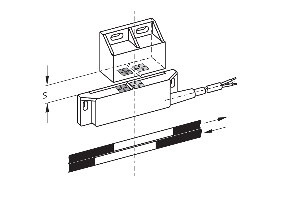
- Actuating surface and direction of actuation marked by switch symbol
- 88 mm x 25 mm x 13 mm
- Thermoplastic enclosure
- Actuating distance up to 60 mm depending on actuating magnet and version
- 2 reed contacts
Ordering data
| Product type description |
BN 310-01Z |
| Article number (order number) |
101133844 |
| EAN (European Article Number) |
4030661059433 |
| eCl@ss number, version 12.0 |
27-27-43-02 |
| eCl@ss number, version 11.0 |
27-27-01-05 |
| eCl@ss number, version 9.0 |
27-27-01-05 |
| ETIM number, version 7.0 |
EC002544 |
| ETIM number, version 6.0 |
EC002544 |
Approvals - Standards
| Certificates |
cULus |
General data
| Working principle |
Transmissão magnética |
| Housing construction form |
retangular |
| Housing material |
Plástico, termoplástico reforçado com fibra de vidro |
| Gross weight |
75 g |
General data - Features
| Suitable for elevators |
Sim |
| Number of normally closed (NC) |
1 |
Mechanical data
| Actuating panels |
lateral |
| Actuating element |
Íman |
| Mechanical lifetime, minimum |
1.000.000.000 Operations |
| Actuating speed, maximum |
18 m/s |
| Mounting |
Invólucro com furos de montagem |
Mechanical data - Switching distances
| Switching distance Sn |
5 mm … 50 mm BP 10 = 5 mm 2 x BP 10 = 17 mm BP 15 = 6 mm 2 x BP 15 = 17 mm 2 x BP 15/2 = 17 mm BP 20 = 20 mm BP 31 = 20 mm BP 12 = 10 ... 30 mm BP 34 = 5 ... 20 mm BP 11 = 8 ... 20 mm BP 21= 25 ... 50 mm BE 20 = 20 mm |
| Note (Switching distance Sn) |
Distância de comutação até 50 mm, dependendo do íman de acionamento ou do modelo. As especificações em relação às distâncias de comutação são válidas em case ao acionar aparelhos individualmente montados sem influência ferromagnética. Uma alteração da distância, tanto positivo como negativo, é possível através de influência ferromagnética. Na disposição de vários ímanes de acionamento deve ser considerada a influência mútua. |
| Note (switching distance) |
All switching distances in accordance EN IEC 60947-5-2 |
| Repeat accuracy R |
0,3 mm |
Mechanical data - Connection technique
| Length of cable |
1 m |
| Termination |
Cabo de ligação |
| Number of cable wires |
2 |
| Wire cross-section |
0,75 mm2 |
| Wire cross-section |
18 AWG |
| Material of the Cable mantle |
PVC |
| Cable type |
H03VV-F |
Mechanical data - Dimensions
| Length of sensor |
13 mm |
| Width of sensor |
88 mm |
| Height of sensor |
25 mm |
Ambient conditions
| Degree of protection |
IP67 |
| Ambient temperature |
-25 ... +75 °C |
| Resistance to vibrations |
10 … 55 Hz, amplitude 1 mm |
| Restistance to shock |
30 g / 11 ms |
Electrical data
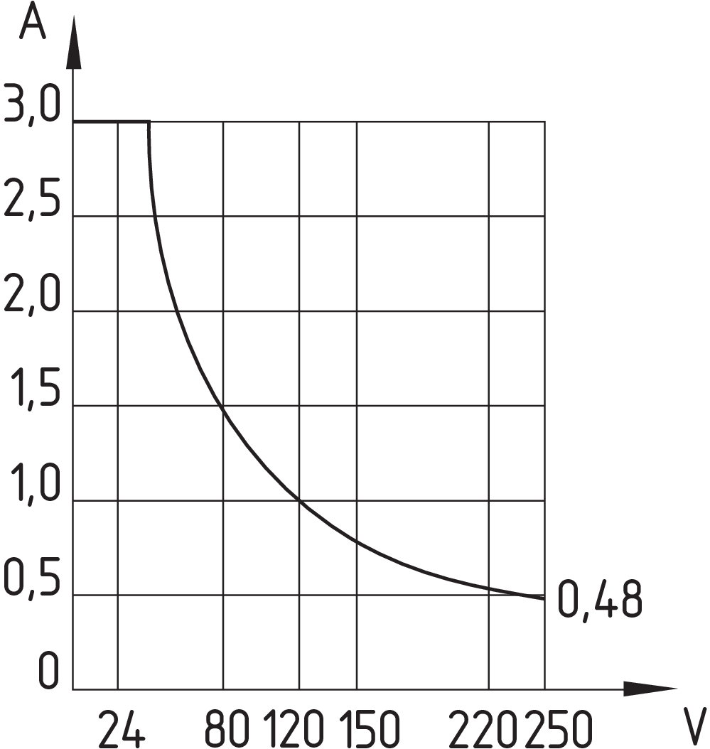
| Switching voltage, maximum |
250 VAC |
| Switching voltage, maximum |
250 VDC |
| Switching current, maximum |
3 A |
| Switching capacity, maximum |
120 W |
| Switching capacity, maximum |
120 VA |
| Switching principle |
Contactos reed, atuação sem contacto físico |
| Bounce duration, minimum |
0,3 ms |
| Bounce duration, maximum |
0,6 ms |
| Switching frequency, maximum |
300 Hz |
| Maximale Schalthäufigkeit |
1.080.000 /h |
| Maximum switching time close (NO) |
1,5 ms |
| Maximum switching time open (NC) |
1,5 ms |
| Switching element |
Normalmente fechado (NF) |
| Minimum switching time close (NO) |
0,3 ms |
Scope of delivery
| Scope of delivery |
O atuador não está incluído no fornecimento. |
Accessory
| Recommendation (actuator) |
BP 10 2x BP 10 BP 15 2x BP 15 2x BP 15/2 BP 34 BP 20 BP 31 BP 11 BP 12 BP 21 BE 20 |
| Recommendation (actuator, lift switchgear) |
BP 10 2 x BP 15/2 2 x BP 15 2 x BP 10 BP 15 BP 34 |
Note
| Note (General) |
A função do NF ou NA depende da direção de acionamento, dos ímanes de acionamento e da polarização dos ímanes de acionamento Quando se colocarem juntos os interruptores magnéticos e os ímanes de acionamento, deve respeitar-se as cores de posicionamento: Vermelho (S) com vermelho(S) e verde (N) com verde (N). Não aplicável para retenção. O interruptor deve ser montado sobre ferro utilizando um calço intermediário, não magnético, com um espessura mínima de 20 mm. |
Filtro de idioma
Ficha técnica
Manual de instruções (anexo/manual breve)
Declaração de conformidade CE
Certificação UL
Informação
Faça download da versão mais recente do Adobe Reader
Foto do produto (foto individual do catálogo )

ID: kbn31f04
| 98,1 kB | .jpg | 352.778 x 97.719 mm - 1000 x 277 px - 72 dpi
| 13,9 kB | .png | 74.083 x 20.461 mm - 210 x 58 px - 72 dpi
| 90,9 kB | .jpg | 352.778 x 97.719 mm - 1000 x 277 px - 72 dpi
| 12,4 kB | .png | 74.083 x 20.461 mm - 210 x 58 px - 72 dpi
| 15,3 kB | .jpg | 123.472 x 34.219 mm - 350 x 97 px - 72 dpi
Desenho dimensional componente básico
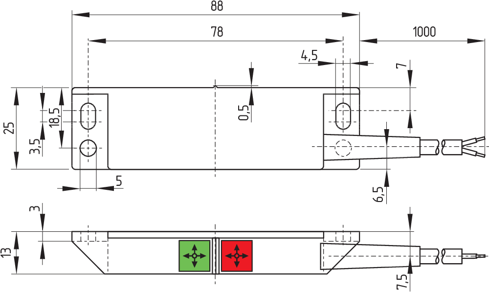
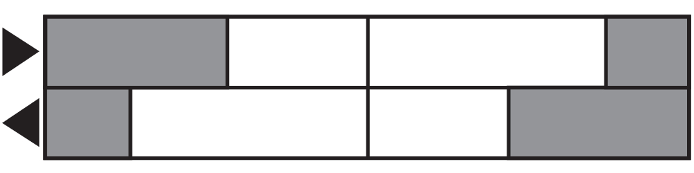
Diagrama das comutações
Diagrama
Curva de característica


Schmersal India Pvt. Ltd., Plot No - G-7/1, Ranjangaon MIDC, Tal. - Shirur, Dist.- Pune 412 220
Os dados e informações anteriores foram verificados cuidadosamente. As imagens podem ser diferentes do original. Mais informações técnicas podem ser encontradas nos manuais de instruções. Sujeito a modificações técnicas e erros.
Gerado em 10/09/2025 00:12