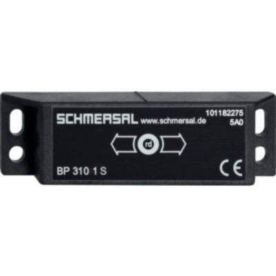
BN 310-RZ

BN 310-RZ
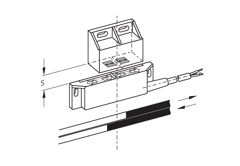
- 1 Reed contakts
- Non-contact principle
- Actuation from side
- Flat design
- Actuating surface and direction of actuation marked by switch symbol
- 88 mm x 25 mm x 13 mm
- Thermoplastic enclosure
- Actuating distance up to 60 mm depending on actuating magnet and version
- 2 reed contacts
Ordering data
| Product type description |
BN 310-RZ |
| Article number (order number) |
101133843 |
| EAN (European Article Number) |
4030661059426 |
| eCl@ss number, version 12.0 |
27-27-43-02 |
| eCl@ss number, version 11.0 |
27-27-01-05 |
| eCl@ss number, version 9.0 |
27-27-01-05 |
| ETIM number, version 7.0 |
EC002544 |
| ETIM number, version 6.0 |
EC002544 |
Approvals - Standards
| Certificates |
cULus |
General data
| Working principle |
Manyetik tahrik |
| Housing construction form |
dikdörtgen |
| Housing material |
Plastik, fiber cam takviyeli termoplastik |
| Gross weight |
65 g |
General data - Features
| Latching |
Evet |
| Suitable for elevators |
Evet |
| Number of snap-in contacts |
1 |
Mechanical data
| Actuating panels |
yan taraf |
| Actuating element |
Mıknatıs |
| Mechanical life, minimum |
1.000.000.000 Operations |
| Actuating speed, maximum |
18 m/s |
| Mounting |
Montaj yuvaları bulunan ek |
Mechanical data - Switching distances according EN IEC 60947-5-3
| Switching distance Sn |
BP 10N = 15 mm BP 10S = 15 mm 2 x BP 10N = 20 mm 2 x BP 10S = 20 mm BP 15N = 17 mm BP 15S = 17 mm 2 x BP 15/2N = 22 mm 2 x BP 15/2S = 22 mm BP 34S = 15 ... 30 mm BP 11N = 15 mm BP 11S = 15 mm BP 12N = 20 mm BP 12S = 20 mm 2 x BP 12N = 10 ... 30 mm 2 x BP 12S = 10 ... 30 mm BP 21N = 15 ... 45 mm BP 21S = 15 ... 45 mm 2 x BP 21N = 20 ... 60 mm 2 x BP 21S = 20 ... 60 mm BE 20N = 20 mm BE 20S = 20 mm 5 mm … 60 mm BP 34N = 15 ... 30 mm BP 20N = 3 ... 25 mm BP 20S = 3 ... 25 mm BP 31N = 3 ... 25 mm BP 31S = 3 ... 25 mm 2 x BP 11N = 3 ... 25 mm 2 x BP 11S = 3 ... 25 mm |
| Note (Switching distance Sn) |
Actuating distance up to 60 mm depending on actuating magnet and version. The specified switching distances are applicable for the actuation of individually mounted components without ferromagnetic influence. A change of the distance, either positive or negative, is possible due to ferromagnetic influences. The mutual interference between multiple actuating magnets must be observed. |
| Repeat accuracy R |
0,3 mm |
Mechanical data - Connection technique
| Length of cable |
1 m |
| Termination |
Kablo |
| Wire cross-section |
0,75 mm2 |
| Wire cross-section |
18 AWG |
| Material of the Cable mantle |
H03VV-F |
Mechanical data - Dimensions
| Length of sensor |
13 mm |
| Width of sensor |
88 mm |
| Height of sensor |
25 mm |
Ambient conditions
| Degree of protection |
IP67 |
| Ambient temperature |
-25 ... +75 °C |
| Resistance to vibrations |
10 … 55 Hz, Genlik 1 mm |
| Restistance to shock |
30 g / 11 ms |
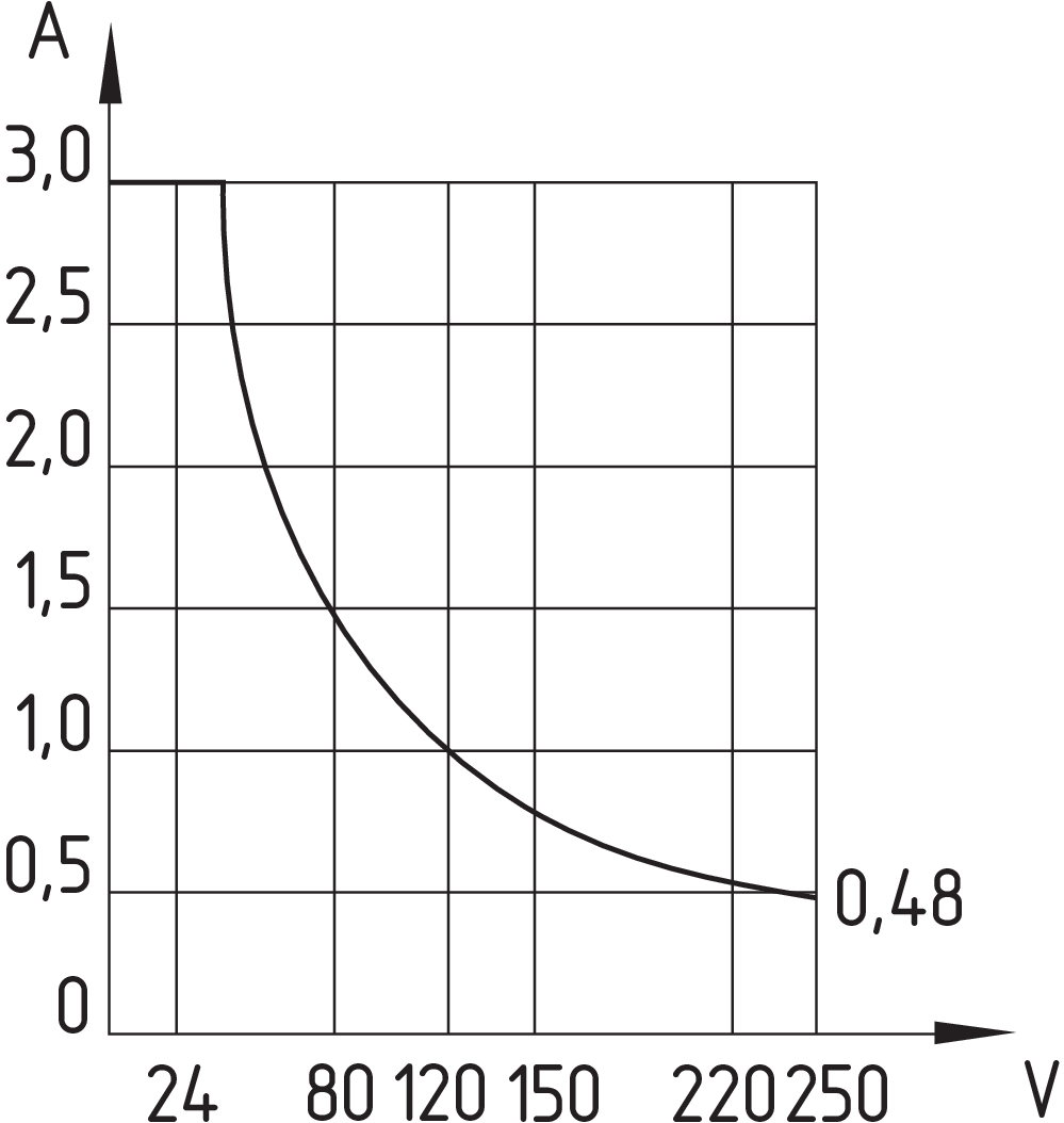
Electrical data
| Switching voltage, maximum |
250 VAC |
| Switching voltage, maximum |
250 VDC |
| Switching current, maximum |
3 A |
| Switching capacity, maximum |
120 W |
| Switching capacity, maximum |
120 VA |
| Switching element |
Bistabil kontakt |
| Bounce duration, minimum |
0,3 ms |
| Bounce duration, maximum |
0,6 ms |
| Switching frequency, maximum |
300 Hz |
Electrical data - Digital Output
| Design of control elements |
Reed kontaktlar |
Scope of delivery
| Scope of delivery |
Actuator must be ordered separately. |
Accessory
| Recommendation (actuator) |
BP 10 S 2x BP 10 S BP 15 S BP 34 S BP 20 S BP 31 S BP 11 S 2x BP 11 S BP 12 S BP 21 S 2x BP 21 S BP 10 N 2x BP 10 N BP 15 N 2 x BP 15/2 N 2x BP 15/2 S BP 34 N BP 20 N BP 31 N BP 11 N 2x BP 11 N BP 12 N 2x BP 12 N 2x BP 12 S BP 21 N 2x BP 21 N BE 20 N(S) ST 24VDC BE 20 N(S) 48VDC |
| Recommendation (actuator, lift switchgear) |
BP 10 2 x BP 15/2 2 x BP 15 2 x BP 10 BP 15 BP 34 |
Note
| Note (General) |
The opening and closing functions depend on the direction of actuation, the actuating magnets and the polarity of the actuating magnets. When the switches and actuators come together, the colours must coincide: Red (S) to red (S) and green (N) to green (N). This does not apply to the bistable contact. The switch is to be mounted on iron with a non-magnetic layer of at least 20 mm. |
Dil filtresi
Veri sayfası
Çalışma talimatları (ek sayfa/hızlı kılavuz)
AB Uygunluk Beyanı
UL Sertifikası
Bilgi
Adobe Reader’ın son sürümünü indirin
Ürün resmi (katalog özel fotoğraf)
Boyutsal resim temel bileşeni

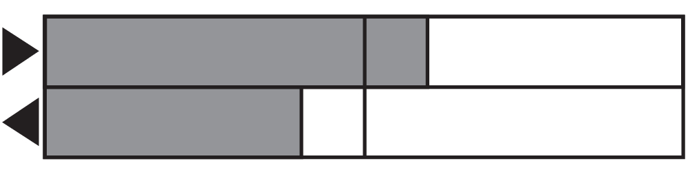
Switch hareket şeması

Switch hareket şeması
Diyagram
Karakteristik eğri

Schmersal India Pvt. Ltd., Plot No - G-7/1, Ranjangaon MIDC, Tal. - Shirur, Dist.- Pune 412 220
Veriler ve ayrıntılar dikkatli bir şekilde kontrol edilmişlerdir. Görüntüler orijinalden farklı olabilir. Daha fazla teknik veri kılavuzda bulunabilir. Teknik değişiklikler ve hatalar olabilir.
Udarbejdet d. 1.04.2025 07:29
