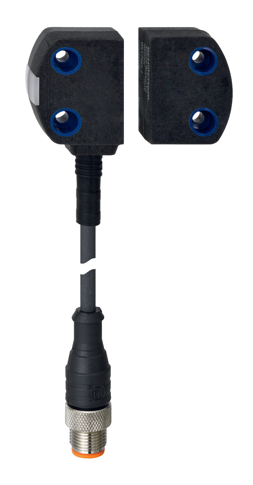
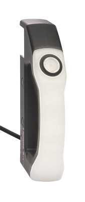
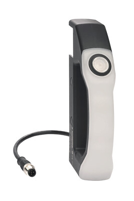
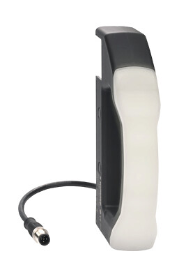
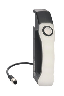
RSS260-D-LSTM12-8-0,25M
RSS260-D-LSTM12-8-0,25M
| Produkt-Typbezeichnung: RSS260-(1)-(2)-(3)-(4)-(5) |
| (1) | |
| ohne | Standard Codierung |
| I1 | Individuelle Codierung |
| I2 | Individuelle Codierung, mehrfach anlernbar |
| (2) | |
| D | Mit Diagnoseausgang |
| SD | Mit serieller Diagnosefunktion 1) |
| (3) | |
| ohne | Standardausführung ohne Rückführkreisüberwachung EDM (External Device Monitoring) |
| F0 | EDM mit automatischem Reset 1) |
| F1 | EDM mit manuellem Reset 1) |
| (4) | |
| ohne | Ohne NOT-HALT |
| Q | Quittieren bei Eingangsfehler durch NOT-HALT 1) |
| (5) | |
| ohne | Anschlussleitung (Länge in m) |
| ST | Einbaustecker M8, 8-polig |
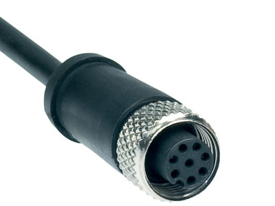
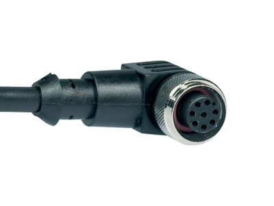
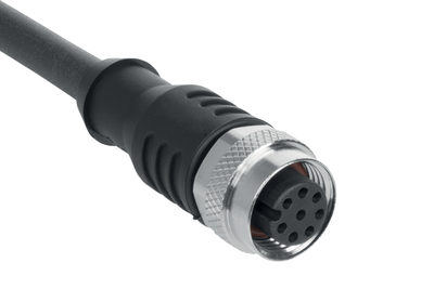
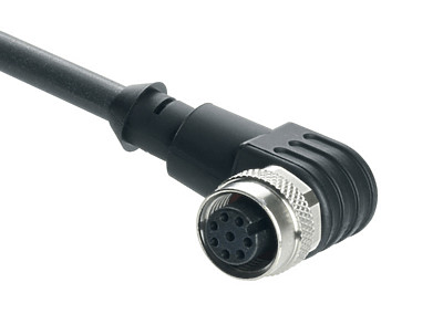
| LSTM12-8-0,25M | Anschlussleitung 0,25 m mit Stecker M12, 8-polig |
| LSTM8-8-0,1M | Anschlussleitung 0,1 m mit Stecker M8, 8-polig |
| LSTM12-5-0,25M | Anschlussleitung 0,25 m mit Stecker M12, 5-polig |
| (*) | |
| 1) | nur für Ausführungen -ST, -LSTM12-8-0,25M und -LSTM8-8-0,1M |
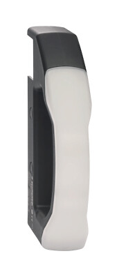
- Simple mounting without additional angle
- Universal coding with RFID technology
- Frontal and lateral actuation enabled
- RFID-technology for needs-based protection against tampering
- 8- pole cable connector M12
- Thermoplastic enclosure
Ordering data
| Product type description |
RSS260-D-LSTM12-8-0,25M |
| Article number (order number) |
103013285 |
| EAN (European Article Number) |
4030661500614 |
| eCl@ss number, version 12.0 |
27-27-46-01 |
| eCl@ss number, version 11.0 |
27-27-24-03 |
| eCl@ss number, version 9.0 |
27-27-24-03 |
| ETIM number, version 7.0 |
EC001829 |
| ETIM number, version 6.0 |
EC001829 |
Approvals - Standards
| Certificates |
TÜV cULus FCC IC ANATEL |
General data
| Standards |
EN ISO 13849-1 EN IEC 60947-5-3 EN IEC 61508 |
| Coding |
Universelle Codierung |
| Coding level according to EN ISO 14119 |
gering |
| Working principle |
RFID |
| Frequency band RFID |
125 kHz |
| Transmitter output RFID, maximum |
-6 dB/m |
| Housing construction form |
Quader |
| Installation conditions (mechanical) |
nicht bündig |
| Sensor topology |
Reihenschaltungsgerät |
| Housing material |
Kunststoff, Thermoplast, selbstverlöschend |
| Active area |
Kunststoff, Thermoplast |
| Reaction time, maximum |
100 ms |
| Duration of risk, maximum |
200 ms |
| Reaction time, switching off safety outputs via actuator, maximum |
100 ms |
| Gross weight |
77 g |
General data - Features
| Diagnostic output |
Ja |
| Short circuit detection |
Ja |
| Cross-circuit detection |
Ja |
| Series-wiring |
Ja |
| Safety functions |
Ja |
| Cascadable |
Ja |
| Integral system diagnostics, status |
Ja |
| Number of LEDs |
3 |
| Number of semi-conductor outputs with signaling function |
1 |
| Number of poles |
8 |
| Number of fail-safe digital outputs |
2 |
| Safety classification |
| Vorschriften |
EN ISO 13849-1 EN IEC 61508 |
| Performance Level, up to |
e |
| Category |
4 |
| PFH value |
6,80 x 10⁻¹⁰ /h |
| PFD value |
1,20 x 10⁻⁴ |
| Safety Integrity Level (SIL), suitable for applications in |
3 |
| Mission time |
20 Year(s) |
Mechanical data
| Actuating panels |
seitlich vorderseitig |
| Active area |
seitlich vorne |
| Mounting |
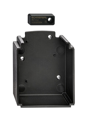
Zur Montage der Sensoren reichen üblicherweise 20 mm Schraubenlänge. Bei Verwendung der Montageplatten werden 25 mm lange Schrauben empfohlen. |
| Type of the fixing screws |
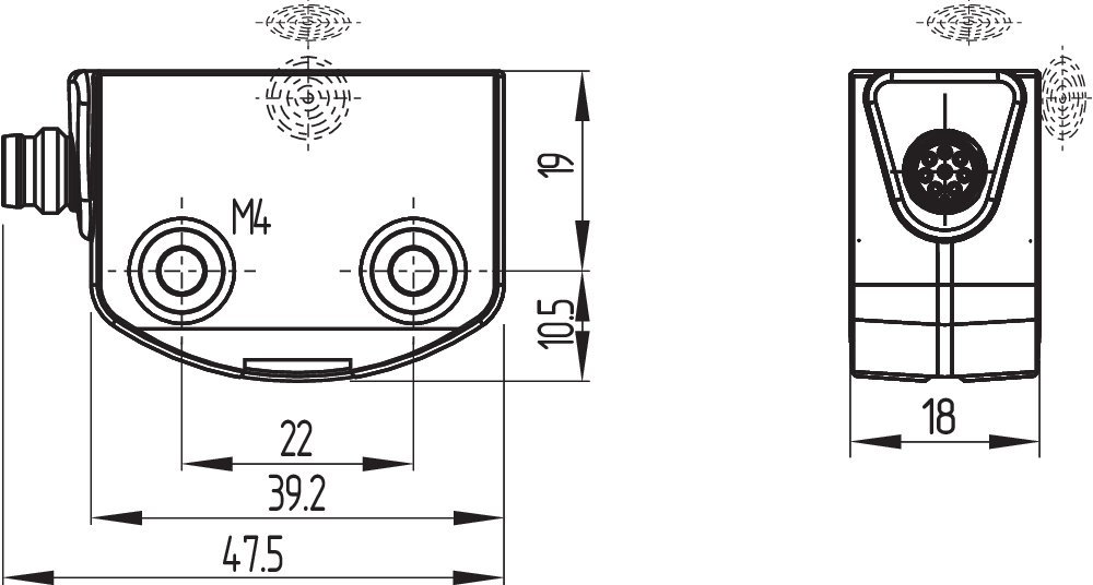
2x M4 |
| Tightening torque of the fixing screws, maximum |
0,8 Nm |
Mechanical data - Switching distances
| Typical switching distance, frontal |
12 mm |
| Typical switching distance, lateral |
9 mm |
| Assured switching distance "ON", frontal |
10 mm |
| Assured switching distance "OFF", frontal |
18 mm |
| Assured switching distance "ON", lateral |
6 mm |
| Assured switching distance "OFF", lateral |
15 mm |
| Note (Sao) |
Die Angaben des gesicherten Schaltabstands Sao beziehen sich auf einen Temperaturbereich −10 °C … +60 °C. Bei einem Temperaturbereich von −28 °C … +65 °C reduziert sich Sao um 2 mm. |
| Note (switching distance) |
Alle Angaben der Schaltabstände gemäß EN IEC 60947-5-3 Axialer Versatz Sicherheits-Sensor und Betätiger tolerieren einen horizontalen und vertikalen Versatz zueinander. Der mögliche Versatz ist abhängig vom Abstand der aktiven Flächen von Sensor und Betätiger. Innerhalb des Toleranzbereiches ist der Sensor aktiv geschaltet. |
| Hysteresis (Switching distance), maximum |
2 mm |
| Repeat accuracy R |
0,5 mm |
| Note (Repeat accuracy R) |
Seitlicher Versatz: Die lange Seitenfläche erlaubt einen max. Höhenversatz (x) von Sensor und Betätiger um 8 mm (z.B. Montagetoleranz oder durch Absacken der Schutztür). Der Querversatz (y) beträgt max. ± 18 mm (siehe Abbildung: Funktionsweise).Mindestabstand von zwei Sensorsystemen 100 mm |
Mechanical data - Connection technique
| Note (length of the sensor chain) |
Leitungslänge und Leitungsquerschnitt verändern den Spannungsfall in Abhängigkeit vom Ausgangsstrom |
| Note (series-wiring) |
Anzahl der Geräte unbegrenzt, externen Leitungsschutz beachten, max. 31 Geräte bei serieller Diagnose SD |
| Termination |
Steckverbinder M12, 8-polig, A-codiert |
Mechanical data - Dimensions
| Length of sensor |
29,5 mm |
| Width of sensor |
39,2 mm |
| Height of sensor |
18 mm |
Ambient conditions
| Degree of protection |
IP65 IP67 |
| Ambient temperature |
-28 ... +65 °C |
| Storage and transport temperature |
-28 ... +85 °C |
| Relative humidity, maximum |
93 % |
| Note (Relative humidity) |
nicht kondensierend nicht vereisend |
| Resistance to vibrations |
10 … 55 Hz, Amplitude 1 mm |
| Restistance to shock |
30 g / 11 ms |
| Permissible installation altitude above sea level, maximum |
2.000 m |
Ambient conditions - Insulation values
| Rated insulation voltage Ui |
32 VDC |
| Rated impulse withstand voltage Uimp |
0,8 kV |
| Overvoltage category |
III |
| Degree of pollution |
3 |
Electrical data
| Operating voltage |
24 VDC -15 % / +10 % (stabilisiertes PELV-Netzteil) |
| Operating current, minimum |
0,5 mA |
| No-load supply current I0, typical |
35 mA |
| Rated operating voltage |
24 VDC |
| Operating current |
600 mA |
| Required rated short-circuit current |
100 A |
| Time to readiness, maximum |
2.000 ms |
| Switching frequency, maximum |
1 Hz |
| Utilisation category DC-12 |
24 VDC / 0,05 A |
| Electrical fuse rating, maximum |
2 A |
Electrical data - Safety digital inputs
| Designation, Safety inputs |
X1 und X2 |
| Current consumption of the safety inputs |
5 mA |
| Test pulse duration, maximum |
1 ms |
| Test pulse interval, minimum |
100 ms |
| Classification ZVEI CB24I, Sink |
C1 |
| Classification ZVEI CB24I, Source |
C1 C2 C3 |
Electrical data - Safety digital outputs
| Designation, Safety outputs |
Y1 und Y2 |
| Rated operating current (safety outputs) |
250 mA |
| Output current, (fail-safe output), maximum |
0,25 A |
| Design of control elements |
kurzschlussfest, p-schaltend |
| Voltage drop Ud, maximum |
1 V |
| Leakage current Ir, maximum |
0,5 mA |
| Voltage, Utilisation category DC-12 |
24 VDC |
| Current, Utilisation category DC-12 |
0,25 A |
| Voltage, Utilisation category DC-13 |
24 VDC |
| Current, Utilisation category DC-13 |
0,25 A |
| Test pulse interval, typical |
1000 ms |
| Test pulse duration, maximum |
1 ms |
| Classification ZVEI CB24I, Source |
C2 |
| Classification ZVEI CB24I, Sink |
C1 C2 |
Electrical data - Diagnostic outputs
| Designation, Diagnostic outputs |
OUT |
| Operating current |
50 mA |
| Voltage drop Ud, maximum |
2 V |
| Voltage, Utilisation category DC-12 |
24 VDC |
| Current, Utilisation category DC-12 |
0,05 A |
| Voltage, Utilisation category DC-13 |
24 VDC |
| Current, Utilisation category DC-13 |
0,05 A |
Electrical data - Electromagnetic compatibility (EMC)
| Interfering radiation |
IEC 61000-6-4 |
Status indication
| Note (LED switching conditions display) |
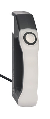
gelbe LED: Betriebszustand grüne LED: Versorgungsspannung rote LED: Fehler |
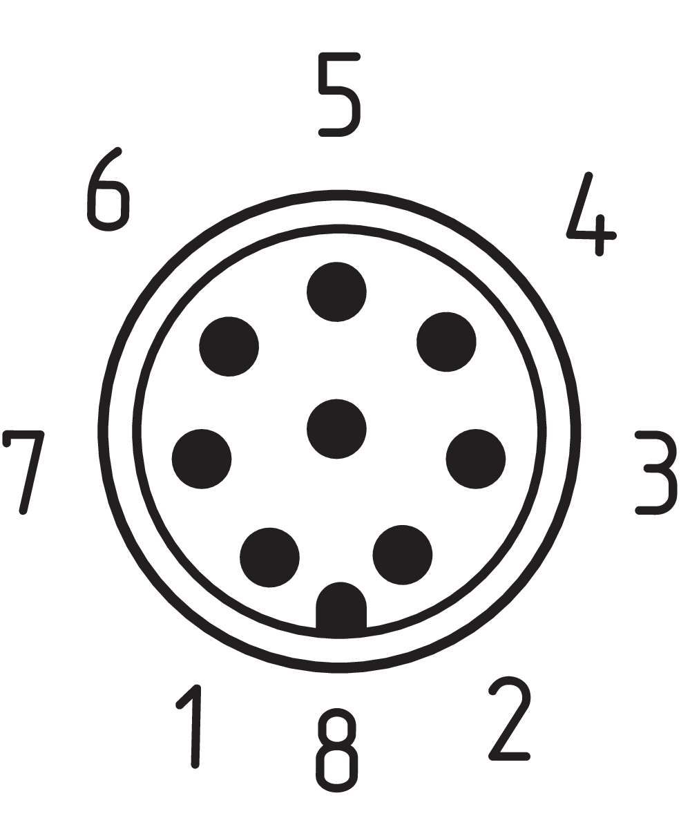
Pin assignment
| PIN 1 |
A1 Versorgungsspannung Ub |
| PIN 2 |
X1 Sicherheitseingang 1 |
| PIN 3 |
A2 GND |
| PIN 4 |
Y1 Sicherheitsausgang 1 |
| PIN 5 |
OUT Diagnoseausgang |
| PIN 6 |
X2 Sicherheitseingang 2 |
| PIN 7 |
Y2 Sicherheitsausgang 2 |
| PIN 8 |
ohne Funktion |
Scope of delivery
| Scope of delivery |
Der Betätiger ist nicht im Lieferumfang enthalten. |
Accessory
| Recommendation (actuator) |
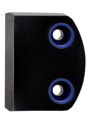
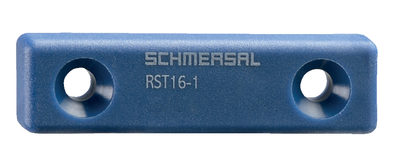
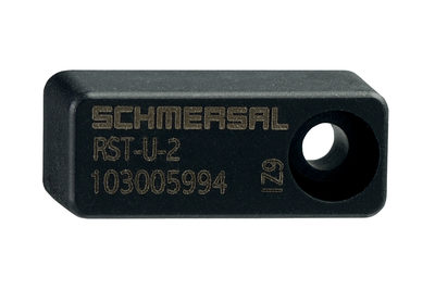
RST16-1 RST-U-2 RST260-1 |
| Recommended safety switchgear |
SRB-E-301ST SRB-E-201LC |
Sprachfilter
Datenblatt
Betriebsanleitung und Konformitätserklärung
UL-Zertifikat
FCC-Zertifikat
IC-Zertifikat
ANATEL-Zertifikat
Broschüre
SISTEMA-VDMA Bibliothek/Library
Download der aktuellen Version von Adobe Reader
Produktbild (Katalogeinzelphoto )
Maßzeichnung Grundgerät
| EU-Konformitätserklärung |  |
| Original | K.A. Schmersal GmbH & Co. KG Möddinghofe 30 42279 Wuppertal Germany Internet: www.schmersal.com |
| Erklärung: | Hiermit erklären wir, dass die nachfolgend aufgeführten Bauteile aufgrund der Konzipierung und Bauart den Anforderungen der unten angeführten Europäischen Richtlinien entsprechen. |
| Bezeichnung des Bauteils: | RSS260 |
| Typ: | siehe Typenschlüssel |
| Beschreibung des Bauteils: | Berührungslos wirkender Sicherheits-Sensor |
| Einschlägige Richtlinien: | Maschinenrichtlinie | 2006/42/EG |
| RED-Richtlinie | 2014/53/EU | |
| RoHS-Richtlinie | 2011/65/EU |
| Angewandte Normen: | EN 60947-5-3:2013 EN 300 330 V2.1.1:2017 EN ISO 14119:2013 EN ISO 13849-1:2023 EN 61508 Teile 1-7:2010 |
| Benannte Stelle der Baumusterprüfung: | TÜV Rheinland Industrie Service GmbH Am Grauen Stein, 51105 Köln Kenn-Nr.: 0035 |
| EG-Baumusterprüfbescheinigung: | 01/205/5348.04/25 |
| Bevollmächtigter für die Zusammenstellung der technischen Unterlagen: | Oliver Wacker Möddinghofe 30 42279 Wuppertal |
| Ort und Datum der Ausstellung: | Wuppertal, 9. Januar 2025 |
 |
| Rechtsverbindliche Unterschrift Philip Schmersal Geschäftsführer |
| UK Declaration of Conformity |  |
| Company: | K.A. Schmersal GmbH & Co. KG Möddinghofe 30 42279 Wuppertal Germany Internet: www.schmersal.com |
| Declaration: | We hereby, under sole responsibility, certify that the hereafter described components both in their basic design and construction conform to the relevant statutory requirements, regulations and designated standards of the United Kingdom. |
| Name of the component: | RSS260 |
| Type: | See ordering code |
| Description of the component: | Non-contact safety sensor |
| Relevant legislation: | Supply of Machinery (Safety) Regulations | 2008 |
| Radio Equipment Regulations | 2017 | |
| The Restriction of the Use of Certain Hazardous Substances in Electrical and Electronic Equipment Regulations | 2012 |
| Designated standards: | EN 60947-5-3:2013 EN 300 330 V2.1.1:2017 EN ISO 14119:2013 EN ISO 13849-1:2015 IEC 61508 parts 1-7:2010 |
| Approved body for Type Examination: | TÜV Rheinland UK Ltd. 1011 Stratford Road Solihull, B90 4BN ID: 2571 |
| Type examination certificate: | 01/205U/5348.00/22 |
| UK-Importer / Person authorised for the compilation of the technical documentation: | Schmersal UK Ltd. Paul Kenney Unit 1, Sparrowhawk Close Enigma Business Park Malvern, Worcestershire, WR14 1GL |
| Place and date of issue: | Wuppertal, November 2, 2022 |
 |
| Authorised signature Philip Schmersal Managing Director |
Schmersal India Pvt. Ltd., Plot No - G-7/1, Ranjangaon MIDC, Tal. - Shirur, Dist.- Pune 412 220
Die genannten Daten und Angaben wurden sorgfältig geprüft. Abbildungen können vom Original abweichen. Weitere technische Daten finden Sie in der Betriebsanleitung. Technische Änderungen und Irrtümer vorbehalten.
Generiert am: 28.06.2025, 05:57
.png?id=497683c97d2c2689df20070a5453bdbb)
