HINGED SAFETY SWITCHES TVS410ST4-11/11A

HINGED SAFETY SWITCHES TVS410ST4-11/11A
Downloads
| Product type description: TVS 410 (1)-(2)(3)(4) |
| (1) | |
| SK | Screw connection |
| CC | Cage clamp |
| ST1 | M12 connector bottom |
| ST2 | M12 connector top |
| (2) | |
| 11/11 | 2 NC contacts / 2 NO contacts (Caution! According to EN 60204-1, the versions with connector must only be used in PELV circuits. Only for ST1, ST2) |
| (3) | |
| U | adjustable switching angle |
| I | Mounting inside (with fixed switching angle 3°) |
| A | Mounting outside (with fixed switching angle 3°) |
| (4) | |
| without | no assembly end stops |
| N | with alignment aid |
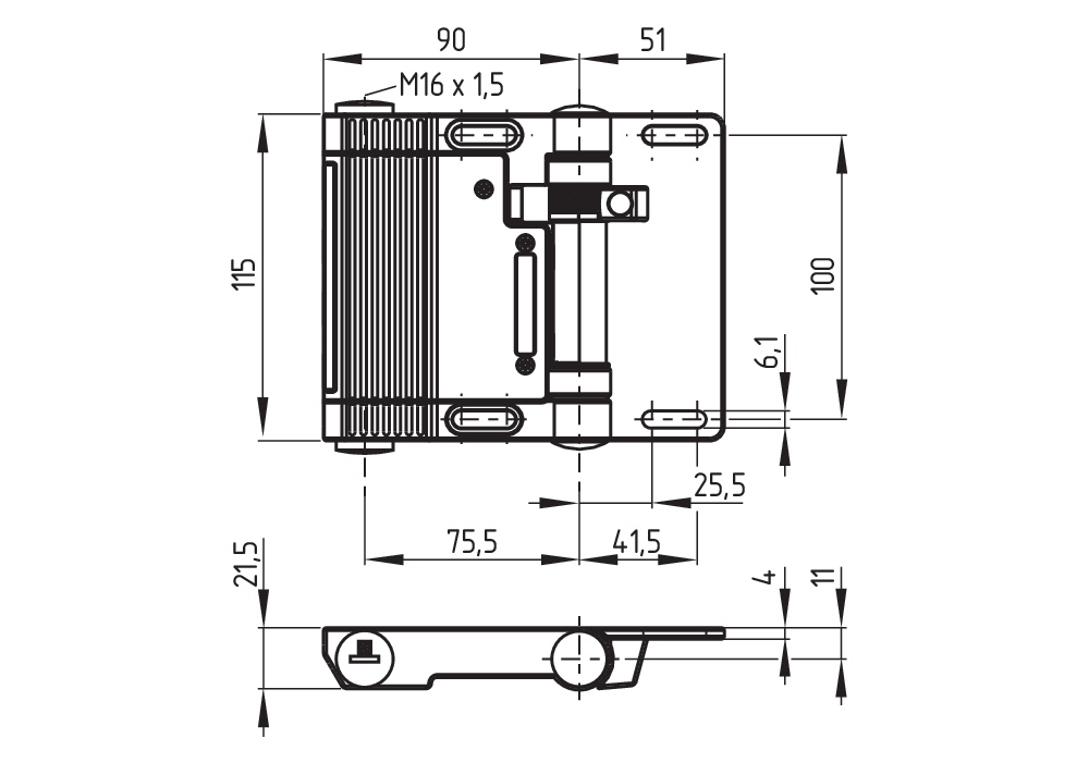
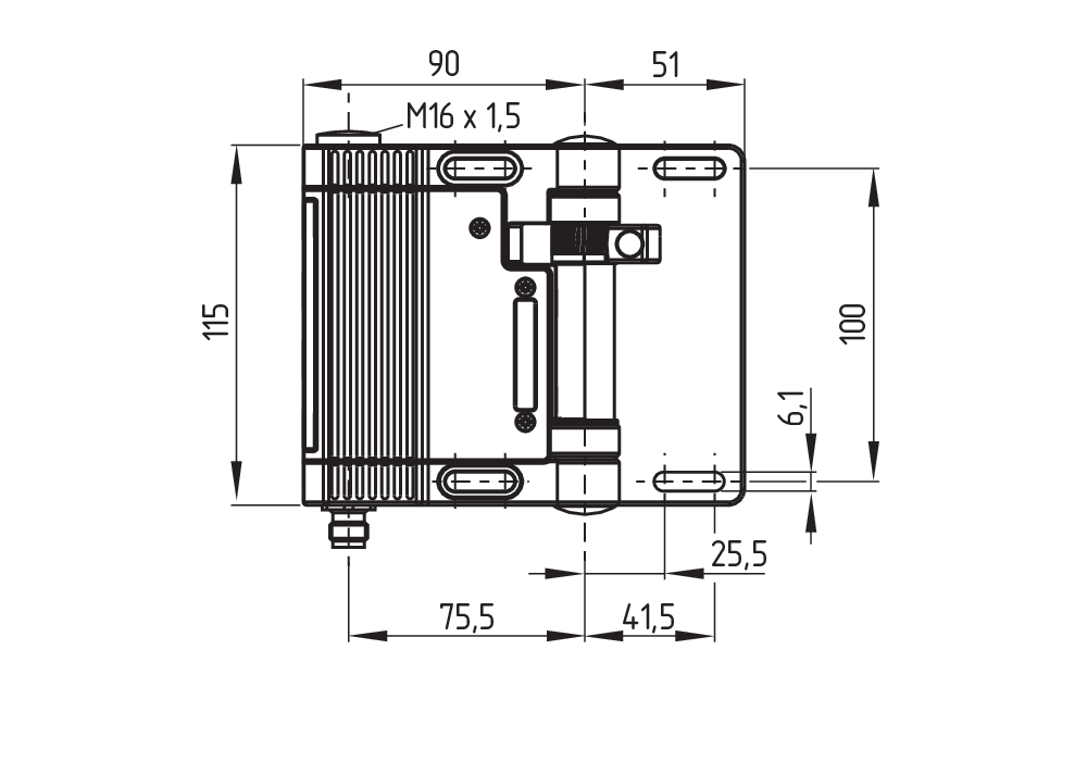
- connector plug M 16 x 1.5, 10-pole, bottom
- with fixed switching angle
- Metal enclosure
- Good resistance to oil and petroleum spirit
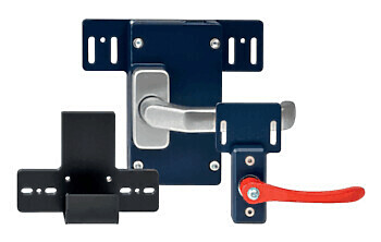
- For left or right hinged doors
- 141 mm x 115 mm x 21,5 mm
- Simple mounting, suitable for all conventional profile systems (30 … 60 mm)
Ordering data
| Note (Delivery capacity) |
Not available! |
| Product type description |
HINGED SAFETY SWITCHES TVS410ST4-11/11A |
| Article number (order number) |
101184434 |
| eCl@ss number, version 12.0 |
27-27-06-09 |
| eCl@ss number, version 11.0 |
27-27-06-09 |
| eCl@ss number, version 9.0 |
27-27-06-09 |
| ETIM number, version 7.0 |
EC002591 |
| ETIM number, version 6.0 |
EC002591 |
General data
| Housing material |
Metal, zinc die-cast |
| Colour of the housing |
Black |
| Gross weight |
640 g |
General data - Features
| Mounting outside |
Yes |
| Number of auxiliary contacts |
2 |
| Number of safety contacts |
2 |
| Safety classification |
| Standards |
BG-GS-ET-15 EN ISO 13849-1 EN IEC 60947-5-1 |
| Mission time |
20 Year(s) |
Safety classification - Safety outputs
| B10D Normally-closed contact (NC) |
2,000,000 Operations |
Mechanical data
| Mechanical lifetime, minimum |
1,000,000 Operations |
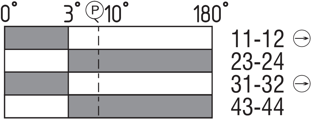
| Positive break angle |
5 ° |
| Opening angle |
180° |
Mechanical data - Connection technique
| Termination |
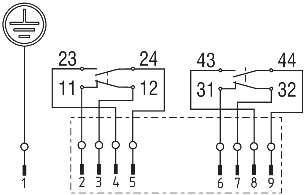
Connector plug M16, 10-pole, bottom Connector M16 |
Mechanical data - Dimensions
| Length of sensor |
21.5 mm |
| Width of sensor |
141 mm |
| Height of sensor |
115 mm |
Ambient conditions
| Degree of protection |
IP65 |
| Ambient temperature |
-25 ... +65 °C |
Ambient conditions - Insulation values
| Rated insulation voltage Ui |
250 VAC |
| Rated impulse withstand voltage Uimp |
2.5 kV |
Electrical data
| Thermal test current |
2.5 A |
| Utilisation category AC-15 |
230 VAC |
| Utilisation category AC-15 |
4 A |
| Utilisation category DC-13 |
24 VDC |
| Utilisation category DC-13 |
1 A |
| Switching element |
NO contact, NC contact |
| Switching principle |
Slow action |
| Maximale Schalthäufigkeit |
1,200 /h |
| Material of the contacts, electrical |
Silver-nickel alloy 10 |
Note
| Note (General) |
Closed guard device = 0° in contact switch travel diagrams. The factory-set switching angle is 3°. Until the limit of the mechanical life has been reached the angle can increase up to 8° under normal wear-out conditions. The positive break angle is 10°. |
Language filter
Datasheet
Operating instructions and Declaration of conformity
Download the latest version of Adobe Reader
Product picture (catalogue individual photo)
Dimensional drawing basic component
Dimensional drawing basic component
Switch travel diagram
Diagram

Schmersal India Pvt. Ltd., Plot No - G-7/1, Ranjangaon MIDC, Tal. - Shirur, Dist.- Pune 412 220
The details and data referred to have been carefully checked. Images may diverge from original. Further technical data can be found in the manual. Technical amendments and errors possible.
Generated on: 15/10/2025, 4:38 pm
Recently viewed