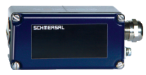
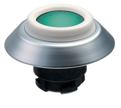
EX-BN 20-20Z-3G/D
EX-BN 20-20Z-3G/D
Downloads
| Product type description: EX-BN 20-(1)Z-3G/D |
| (1) | |
| 01 | 1 NC contact |
| 02 | 2 NC contact |
| 10 | 1 NO contact |
| 20 | 2 NO contacts |
| 11 | 1 NC contacts / 1 NO contact |
| R | 1 bistable contact |
| 2R | 2 bistable contact |
| 11R | 2 bistable contact NC / NO |
- 2 reed contacts
- Explosion protection for ATEX Zones 2 and 22
- Aluminium enlosure
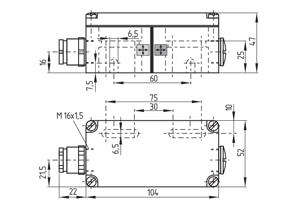
- 104 mm x 52 mm x 47 mm
- Actuating distance up to 50 mm depending on actuating magnet and version
- Non-contact principle
- Screw connection
Ordering data
| Product type description |
EX-BN 20-20Z-3G/D |
| Article number (order number) |
101194601 |
| EAN (European Article Number) |
4030661359007 |
| eCl@ss number, version 12.0 |
27-27-43-02 |
| eCl@ss number, version 11.0 |
27-27-01-05 |
| eCl@ss number, version 9.0 |
27-27-01-05 |
| ETIM number, version 7.0 |
EC002544 |
| ETIM number, version 6.0 |
EC002544 |
Approvals - Standards
| Certificates |
ATEX (Konformitätserklärung) |
Explosion protection
| Explosion protection: regulations |
EN IEC 60079-0 EN IEC 60079-15 EN 60079-31 |
| Explosion protection zones |
2 22 |
| Explosion protection category |
3G 3D |
| Explosion protection designation |
D II 3G Ex nC IIC T5 Gc X D II 3D Ex tc IIIC T90°C Dc X |
| Manufacturer declaration |
ATEX Zone 2 and 22 |
General data
| Working principle |
Magnetic drive |
| Housing construction form |
rectangular |
| Housing material |
Light-alloy diecast, paint finish |
| Active area |
Metal film |
| Gross weight |
326 g |
General data - Features
| bias magnet |
Yes |
| Number of normally open (NO) |
2 |
Mechanical data
| Actuating panels |
lateral |
| Active area |
lateral |
| Actuating element |
Magnet |
| Mechanical life, minimum |
1,000,000,000 Operations |
| Impact energy, maximum |
4 J |
| Actuating speed, maximum |
18 m/s |
Mechanical data - Switching distances
| Switching distance Sn |
12 mm ... 45 mm |
| Note (Switching distance Sn) |
Actuating distance up to 45 mm depending on version and actuating magnet |
| Note (switching distance) |
All switching distances in accordance EN IEC 60947-5-2 |
| Repeat accuracy R |
0.3 mm |
Mechanical data - Connection technique
| Termination |
Screw terminals M20 x 1.5 |
| Cable cross-section of the cable glands, minimum |
6 mm |
| Cable cross-section of the cable glands, maximum |
10 mm |
Mechanical data - Dimensions
| Length of sensor |
47 mm |
| Width of sensor |
104 mm |
| Height of sensor |
52 mm |
Ambient conditions
| Degree of protection |
IP67 |
| Ambient temperature |
-15 ... +70 °C |
| Storage and transport temperature |
-20 ... +70 °C |
| Resistance to vibrations |
10 … 55 Hz, amplitude 1 mm |
| Restistance to shock |
30 g / 11 ms |
| Resistant to vibration |
50 g, on sine wave oscillation |
Electrical data
| Switching voltage, maximum |
250 VAC |
| Switching voltage, maximum |
250 VDC |
| Switching current, maximum |
3 A |
| Switching capacity, maximum |
120 W |
| Switching capacity, maximum |
120 VA |
| Switching element |
Normally open contact (NO) |
| Switching principle |
Reed contacts, Non-contact principle |
| Bounce duration, minimum |
0.3 ms |
| Bounce duration, maximum |
0.6 ms |
Scope of delivery
| Scope of delivery |
Actuator must be ordered separately. Ex-certified screwed cable gland |
Accessory
| Recommendation (actuator) |
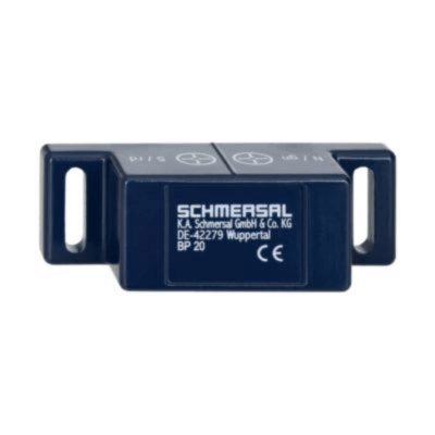
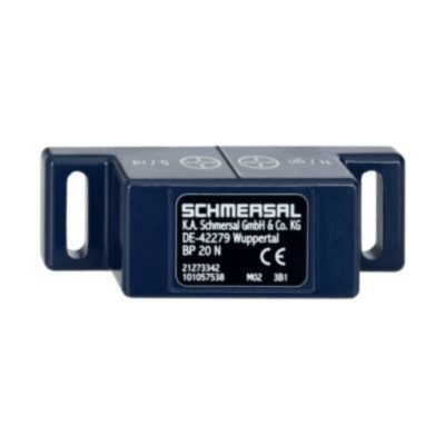
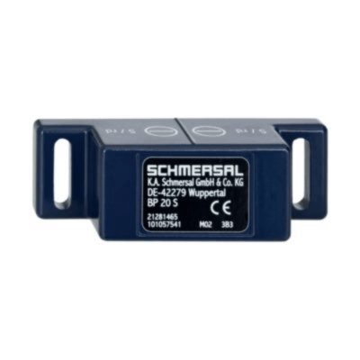
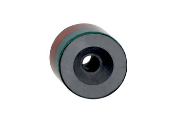
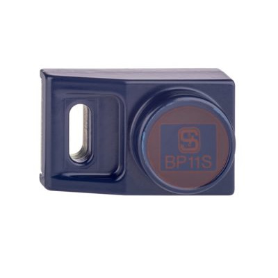
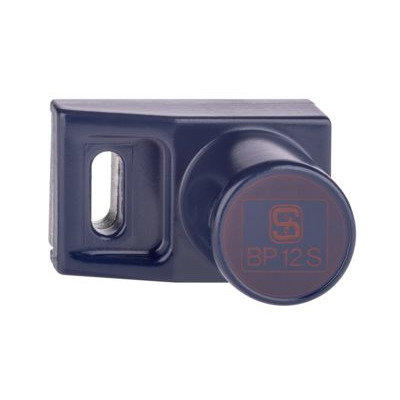
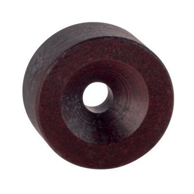
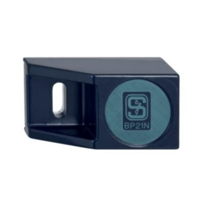
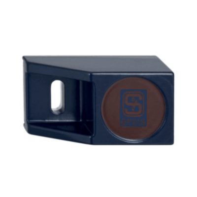
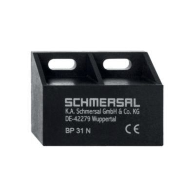
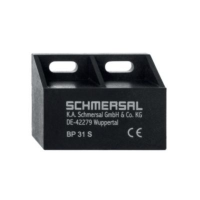
2x BP 10 2x BP 15/2 BP 20 BP 31 BP 11 BP 12 BP 21 BE 20 |
Note
| Note (General) |
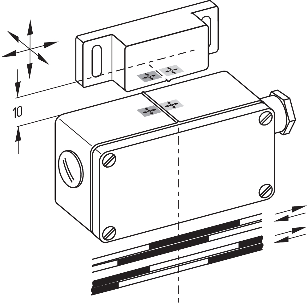
The opening and closing functions depend on the direction of actuation, the actuating magnets and the polarity of the actuating magnets. When the switches and actuators come together, the colours must coincide: Red (S) to red (S) and green (N) to green (N). |
Language filter
Datasheet
Operating instructions and Declaration of conformity
Info
Download the latest version of Adobe Reader
Product picture (catalogue individual photo)
Dimensional drawing basic component
Diagram
Characteristic curve
| EU Declaration of Conformity |  |
| Original | K.A. Schmersal GmbH & Co. KG Möddinghofe 30 42279 Wuppertal Germany Internet: www.schmersal.com |
| Declaration: | We hereby certify that the hereafter described components both in their basic design and construction conform to the applicable European Directives. |
| Name of the component: | EX-BN 20 |
| Type: | See ordering code |
| Marking: | D II 3G Ex nC IIC T5 Gc X D II 3D Ex tc IIIC T90°C Dc X |
| Description of the component: | Magnetic reed switches |
| Relevant Directives: | Explosion Protection Directive (ATEX) | 2014/34/EU |
| RoHS-Directive | 2011/65/EU |
| Applied standards: | EN IEC 60079-0:2018 EN IEC 60079-15:2019 EN 60079-31:2014 |
| Notified body, which approved the full quality assurance system, referred to Appendix IV, 2014/34/EU: | TÜV Rheinland Industrie Service GmbH Am Grauen Stein, 51105 Köln ID n°: 0035 |
| Person authorised for the compilation of the technical documentation: | Oliver Wacker Möddinghofe 30 42279 Wuppertal |
| Place and date of issue: | Wuppertal, September 21, 2023 |
 |
| Authorised signature Philip Schmersal Managing Director |
K.A. Schmersal GmbH & Co. KG, Möddinghofe 30, 42279 Wuppertal
The details and data referred to have been carefully checked. Images may diverge from original. Further technical data can be found in the manual. Technical amendments and errors possible.
Generated on: 05/08/2025, 04:47
.png?id=bb44e9061d048e5250879d3fc4285be0)
