ACC-AZM40-LEV-T-Test

ACC-AZM40-LEV-T-Test
Téléchargements
| Product type description: ACC-AZM40-(1)-(2)-(3) |
| (1) | |
| LEV | Lever |
| PT | push button |
| (2) | |
| T | Emergency exit |
| N | Emergency release |
| (3) | |
| 40 mm | for door stile thicknesses up to 40 mm (only for PT version) |
| 170 mm | for door stile thicknesses up to 170 mm (only for PT version) |
Exemple de commande
| Désignation de type du produit |
ACC-AZM40-LEV-T-Test |
| Référence d’article (n° de commande) |
999992020 |
| EAN (European Article Number) |
4030661640327 |
Caractéristiques globales
| Matériau du boîtier |
Plastique, thermoplastique renforcé de fibres de verre, auto-extinguible |
| Matériau de l' élément d'actionnement |
Plastic, glass-fibre reinforced thermoplastic, self-extinguishing |
| Couleur de l'élément de commande |
rouge |
Données générales - Caractéristiques
| Déverrouillage de secours |
Oui |
Données mécaniques
| Tightening torque of the screw for release socket |
0,55 Nm |
| Type of the fixing screws, release socket |
M2 x 13 (TX6) |
Données mécaniques - Dimensions
| Longueur |
44 mm |
| Largeur |
20 mm |
| Hauteur |
15 mm |
Photo du produit (photo individuelle de catalogue)
Table of Contents
- 1 About this document
- 1.1 Function
- 1.2 Target group of the operating instructions: authorised qualified personnel
- 1.3 Explanation of the symbols used
- 1.4 Appropriate use
- 1.5 General safety instructions
- 1.6 Warning about misuse
- 1.7 Exclusion of liability
- 2 Product description
- 2.1 Ordering code
- 2.2 Special versions
- 2.3 Purpose
- 2.4 Technical Data
- 3 Mounting
- 3.1 General mounting instructions
- 3.2 Manual release
- 3.3 Dimensions
- 4 Electrical connection
- 4.1 General information for electrical connection
- 4.2 Requirements for the connected safety-monitoring module
- 4.3 Wiring configuration and connector accessories
- 4.4 Wiring examples
- 5 Actuator teaching / actuator detection
- 6 Active principle and diagnostic functions
- 6.1 Magnet control
- 6.2 Mode of operation of the safety outputs
- 6.3 Diagnostic-LEDs
- 6.4 Diagnostic outputs
- 6.5 Diagnostic information
- 7 Set-up and maintenance
- 7.1 Functional testing
- 7.2 Maintenance
- 8 Disassembly and disposal
- 8.1 Disassembly
- 8.2 Disposal
1 About this document
1.1 Function
This document provides all the information you need for the mounting, set-up and commissioning to ensure the safe operation and disassembly of the switchgear. The operating instructions enclosed with the device must always be kept in a legible condition and accessible.
1.2 Target group of the operating instructions: authorised qualified personnel
All operations described in the operating instructions manual must be carried out by trained specialist personnel, authorised by the plant operator only.
Please make sure that you have read and understood these operating instructions and that you know all applicable legislations regarding occupational safety and accident prevention prior to installation and putting the component into operation.
The machine builder must carefully select the harmonised standards to be complied with as well as other technical specifications for the selection, mounting and integration of the components.
1.3 Explanation of the symbols used
- Information, hint, note: This symbol is used for identifying useful additional information.
- Caution: Failure to comply with this warning notice could lead to failures or malfunctions.
Warning: Failure to comply with this warning notice could lead to physical injury and/or damage to the machine.
1.4 Appropriate use
The Schmersal range of products is not intended for private consumers.
The products described in these operating instructions are developed to execute safety-related functions as part of an entire plant or machine. It is the responsibility of the manufacturer of a machine or plant to ensure the correct functionality of the entire machine or plant.
The safety switchgear must be exclusively used in accordance with the versions listed below or for the applications authorised by the manufacturer. Detailed information regarding the range of applications can be found in the chapter "Product description".
1.5 General safety instructions
The user must observe the safety instructions in this operating instructions manual, the country specific installation standards as well as all prevailing safety regulations and accident prevention rules.
- Further technical information can be found in the Schmersal catalogues or in the online catalogue on the Internet: products.schmersal.com.
The information contained in this operating instructions manual is provided without liability and is subject to technical modifications.
There are no residual risks, provided that the safety instructions as well as the instructions regarding mounting, commissioning, operation and maintenance are observed.
1.6 Warning about misuse
- In case of inadequate or improper use or manipulations of the component, personal hazards or damage to machinery or plant components cannot be excluded.
1.7 Exclusion of liability
We shall accept no liability for damages and malfunctions resulting from defective mounting or failure to comply with the operating instructions manual. The manufacturer shall accept no liability for damages resulting from the use of unauthorised spare parts or accessories.
For safety reasons, invasive work on the device as well as arbitrary repairs, conversions and modifications to the device are strictly forbidden, the manufacturer shall accept no liability for damages resulting from such invasive work, arbitrary repairs, conversions and/or modifications to the device.
2 Product description
2.1 Ordering code
| Product type description: AZM40(1)-(2)-ST-1P2P-(3) |
| (1) | |
| Z | Guard locking monitoring > |
| B | Actuator monitoring |
| (2) | |
| without | Standard coding |
| I1 | Individual coding |
| I2 | Individual coding, re-teaching enabled |
| (3) | |
| without | Counterbores for countersunk screws (standard) |
| PH | Flat enclosure for protruding screws |
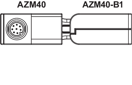
| Actuator | AZM40-B1 |
| AZM40-B1-PH |
2.2 Special versions
For special versions, which are not listed in the ordering code, these specifications apply accordingly, provided that they correspond to the standard version.
2.3 Purpose
The non-contact, electronic safety switchgear is designed for application in safety circuits and is used for monitoring the position and locking of movable safety guards.
The AZM40 interlock system is suitable for mounting to 40 mm profile systems and, thanks to the 180 degree angle flexibility of the actuator, for rotating and sliding guards. LEDs are visible from 3 sides.
- The safety switchgears are classified according to EN ISO 14119 as type 4 interlocking devices. Designs with individual coding are classified as highly coded.
The different variants can be used as safety switch with interlocking function either as solenoid interlock.
- If the risk analysis indicates the use of a monitored interlock then a variant with the monitored interlock is to be used, marked with the > symbol in the ordering code.
The actuator monitoring variant (B) is a safety switch with an interlock function for process protection.
The safety function consists of safely switching off the safety outputs when the safety guard is unlocked or opened and maintaining the safe switched off condition of the safety outputs for as long as the safety guard is open.
The AZM40 solenoid interlock is a bi-stable system, which means the interlock remains in the last position if power is lost.
Series-wiring
Series-wiring can be set up. In the case of a series connection, the risk time remains unchanged and the reaction time increases by the sum of the reaction time of the inputs per additional unit specified in the technical data. The quantity of devices is only limited by the cable drops and the external cable fuse protection, according to the technical data.
- The user must evaluate and design the safety chain in accordance with the relevant standards and the required safety level. If multiple safety sensors are involved in the same safety function, the PFH values of the individual components must be added.
- The entire concept of the control system, in which the safety component is integrated, must be validated to the relevant standards.
2.4 Technical Data
Caractéristiques globales
| Matériau du boîtier |
Plastique, thermoplastique renforcé de fibres de verre, auto-extinguible |
| Matériau de l' élément d'actionnement |
Plastic, glass-fibre reinforced thermoplastic, self-extinguishing |
| Couleur de l'élément de commande |
rouge |
Données générales - Caractéristiques
| Déverrouillage de secours |
Oui |
Données mécaniques
| Tightening torque of the screw for release socket |
0,55 Nm |
| Type of the fixing screws, release socket |
M2 x 13 (TX6) |
Données mécaniques - Dimensions
| Longueur |
44 mm |
| Largeur |
20 mm |
| Hauteur |
15 mm |
Note about the safety classification
- The safety classification of the guard locking function only applies for standard devices with monitored solenoid interlock AZM40Z-…-1P2P-… (see Ordering code).
- The actuation of the interlock must be compared externally with the OSSD release. If a shut-down now occurs due to an unintentional unlocking this is detected by an external diagnostic.
- The safety analysis of the guard locking function refers to the component solenoid interlock AZM as part of the complete system.
On the customer side further measures such as safe actuation and safe cable installation to prevent faults are to be implemented.
In the event of a fault resulting in the unlocking of the guard locking, this is detected by the solenoid interlock and the safety gates Y1/Y2 switch off. When such a fault occurs the protection equipment may open immediately, just once, before the safe condition of the machine is reached. The system reaction of category 2 allows that a fault can occur between tests causing the loss of the safety function which is detected by the test.
FCC/IC - Note
This device complies with Part 15 of the FCC Rules and contains licence-exempt transmitter/receivers that are compliant with ISED (Innovation, Science and Economic Development) Canada licence-exempt RSS standard(s).
Operation is subject to the following two conditions:
(1) This device may not cause harmful interference signals, and
(2) This device must be able to tolerate interference signals. These also include interference signals that could cause the device to function improperly.
This device complies with the nerve stimulation limits (ISED SPR-002) when operated at a minimum distance of 100 mm. Changes or modifications not expressly approved by K.A. Schmersal GmbH & Co. KG could void the user's authority to operate the equipment.
The licence-free transmitter/receiver contained in this device satisfies the requirements of the "Radio Standards Specification" of the Innovation, Science and Economic Development Canada (ISED) authority that apply to licence-free radio equipment. Operation is permissible under the following two conditions:
(1) The device must not create disturbances.
(2) The device must tolerate received radio frequency interference, even if this could impair its functionality.
This device complies with the nerve stimulation limits (ISED CNR-102) when operated at a minimum distance of 100 mm.
In the event of changes or modifications that have not been expressly approved by K.A. Schmersal GmbH & Co. KG, the user's authorisation to use the device may become ineffective.
| 20941-22-14519 | Este equipamento nao tem direito àprotecao contra interferência prejudicial e nao pode causar interferencia em sistemas devidamente autorizados. Para maiores informacores consultar: www.gov.br/anatel |
3 Mounting
3.1 General mounting instructions
- Please observe the remarks of the standards EN ISO 12100, EN ISO 14119 and EN ISO 14120.
Any position is possible.
The solenoid interlock must not be used as an end stop.
The transport lock must be removed.
For attachment of the solenoid interlock and the actuator, two mounting holes for M5 screws are provided.
- The M5 screws must be at least strength class 8.8 or, in stainless steel, strength class 80. The tightening torque of the M5 screws is 4 ... 6 Nm, the maximum tightening torque depends on the fastening screws used.
- The solenoid interlock is self-greasing. The grease on the locking bolt and in the actuator recess must not be removed.
- The accumulation of fine-grained dirt in the bolt area must be avoided. In that case, mounting where the bolt goes upwards from below is not advisable.
The actuator must be mounted so that it is protected from damage due to external influences.
- Use in temperatures below freezing is permitted only with dry cold. The customer must take this into account when assembling the safety switch.
- The interlock with locking bolt (A) and actuator with triangular marking (B) must be installed in the same installation direction.
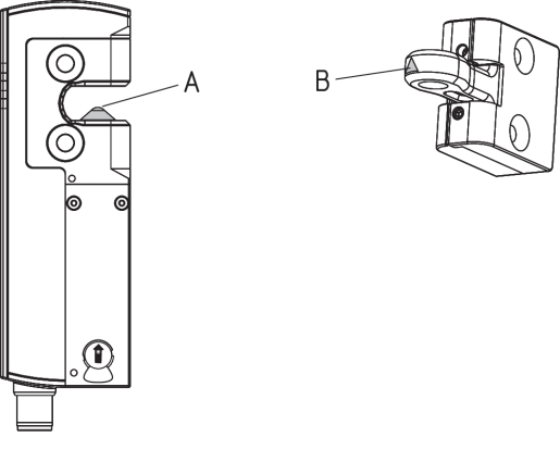
Actuation direction
The actuator can be continuously inserted by 180°.

- The actuator must be permanently fitted to the safety guards and protected against displacement by suitable measures (tamperproof screws, gluing, drilling of the screw heads).
Authorised actuator and interlock offset
| Tilt angle | Rotating angle |
|---|---|
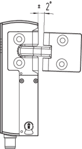 |  |
| Actuating directions and switch distances | ||
|---|---|---|
| The AZM40 can be operated within the following tolerance limits: | ||
| X axis | - 3 mm |  |
| Y axis | ± 1 mm | |
| Z axis | ± 1.5 mm (actuator in centre position) | |
Adjustment
The two hexagon socket screws M4 can be used to adjust the actuator tongue in the X direction, using a hexagonal key wrench AF 2 mm.
Adjustment via hexagon socket screws M4Local

- The hexagon socket screws must not be completely unscrewed.
To avoid any interference inherent to this kind of system and any reduction of the switching distances, please observe the following guidelines:
- Metal parts and magnetic fields in the area of the solenoid interlock and the actuator can influence the switch distance or lead to malfunctions
- Keep away from metal chips
Minimum distance between AZM40 solenoid interlocks (in mm)

3.2 Manual release
For installation and maintenance, the solenoid interlock can be unlocked in a de-energised condition. The solenoid interlock is unlocked by turning the auxiliary release anti-clockwise. The normal locking function is only restored after the manual release has been returned to its original position.
- Do not turn the manual release beyond the end stop.
A tool is required to operate the manual release (recommendation: slotted screwdriver 0.8 x 4 ... 4.5 mm).
The manual release must be protected against accidental actuation, e.g. by using the enclosed seal after completing commissioning.

| Key | |
|---|---|
| A | Connector plug M12, 8-pole |
| B | LED indications |
| C | Manual release (on both sides) |
 | Solenoid interlock ready for operation |
 | Solenoid interlock not ready for operation |
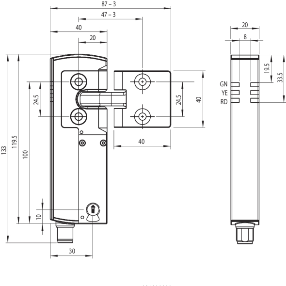
3.3 Dimensions
All measurements in mm.
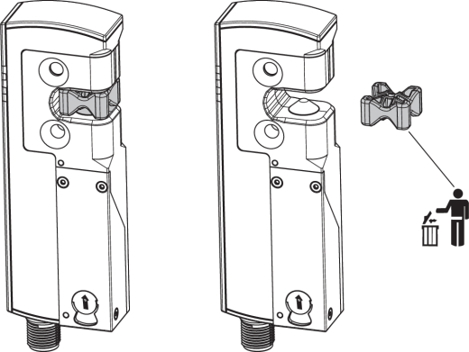
Retrofit kit emergency exit/emergency release
The retrofit kit is used for subsequent functional expansion of the solenoid interlock.
| Designation | Ordering code | |
|---|---|---|
| Emergency exit | ACC-AZM40-LEV-T | 103054265 |
| Emergency release | ACC-AZM40-LEV-N | 103054268 |
| Emergency exit with pushbutton - for 40 mm profiles - for profiles up to 170 mm | ACC-AZM40-PT-T-40MM ACC-AZM40-PT-T-170MM | 103054271 103054273 |
| Emergency release with push button - for 40 mm profiles - for profiles up to 170 mm | ACC-AZM40-PT-N-40MM ACC-AZM40-PT-N-170MM | 103054275 103054277 |
| ACC-AZM40-LEV | ACC-AZM40-PT |
|---|---|
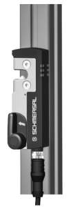 | 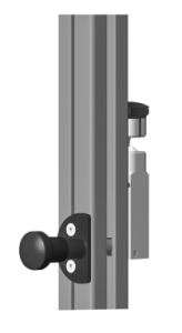 |
| Designation | Ordering code | |
|---|---|---|
| Lockout device | SZ40 | 103053182 |
| Universal mounting plate, for 20, 30, 45, 50 and 60 mm profile systems, 2 pcs. | MP-AZM40 | 103045324 |
| Tamper-proof screws M5 x 25, flat head, 2 pcs. | ACC-NRS-M5X25-FHS-2PCS | 103045415 |
| Tamper-proof screws M5 x 25, countersunk head, 2 pcs. | ACC-NRS-M5X25-CSS-2PCS | 103045416 |
| SZ40 | MP-AZM40 |
|---|---|
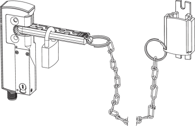 | 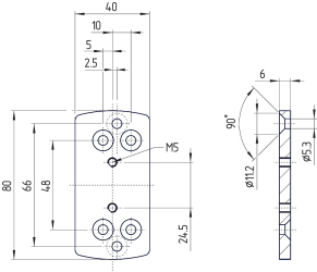 |
4 Electrical connection
4.1 General information for electrical connection
- The electrical connection may only be carried out by authorised personnel in a de-energised condition.
The voltage inputs A1, X1, X2 and IN must have a protection against permanent overvoltage. Supply units according to EN 60204-1 is recommended.
The required electrical cable fuse protection must be integrated in the installation.
The safety outputs can be integrated into the safety circuit of the control system.
4.2 Requirements for the connected safety-monitoring module
Dual-channel safety input, suitable for 2 p-type semi-conductor outputs (OSSD)
- Safety controller configuration
If the safety switchgear is connected to electronic safety-monitoring modules, we recommend that you set a discrepancy time of at least 100 ms. The safety inputs of the safety-monitoring module must be able blanking a test impulse of approx. 1 ms. The safety-monitoring module does not need to have a cross-wire short monitoring function, if necessary, the cross-wire short monitoring function must be disabled.
- Information for the selection of suitable safety-monitoring modules can be found in the Schmersal catalogues or in the online catalogue on the Internet: products.schmersal.com
4.3 Wiring configuration and connector accessories
| Function safety switchgear | Pin configuration of the connector | Colour code of conductor numbering of Schmersal connector plugs | Poss. Colour code of other commercially available connector plugs according to EN 60947-5-2 | |||
|---|---|---|---|---|---|---|
| With conventional diagnostic output |  | P67 / IP69 acc. DIN 47100 | IP69 (PVC) | |||
| A1 | Ue | 1 | WH | BN | BN | |
| X1 | Safety input 1 | 2 | BN | WH | WH | |
| A2 | GND | 3 | GN | BU | BU | |
| Y1 | Safety output 1 | 4 | YE | BK | BK | |
| OUT | Diagnostic output | 5 | GY | GY | GY | |
| X2 | Safety input 2 | 6 | PK | VT | PK | |
| Y2 | Safety output 2 | 7 | BU | RD | VT | |
| IN | Magnet control | 8 | RD | PK | OR | |
Accessories Pre-wired cables
| Pre-wired cables with socket (female) M12, 8-pole - 8 x 0.25 mm², IP67 / IP69 | |
|---|---|
| Cable length | Ordering code |
| 2.5 m | 103011415 |
| 5.0 m | 103007358 |
| 10.0 m | 103007359 |
| 15.0 m | 103011414 |
| Connecting cables (PVC) with socket (female) M12, 8-pole - 8 x 0.21 mm², IP69 | |
|---|---|
| Cable length | Ordering code |
| 5.0 m | 101210560 |
| 5.0 m, angled | 101210561 |
| 10.0 m | 103001389 |
| 15.0 m | 103014823 |
Further versions in other lengths and with angled cable exit are available upon request.
- When using an angled connector, it is aligned parallel to the attachment surface and points to the side away from the actuator.
4.4 Wiring examples
The application examples shown are suggestions. They however do not release the user from carefully checking whether the switchgear and its set-up are suitable for the individual application. The application examples shown are suggestions.
Wiring example: Series-wiring AZM40
The voltage is supplied at both safety inputs of the terminal safety component of the chain (considered from the safety-monitoring module). The safety outputs of the first safety component are wired to the safety-monitoring module.

Y1 and Y2 = Safety outputs → Safety monitoring module
5 Actuator teaching / actuator detection
Solenoid interlocks with standard coding are ready to use upon delivery.
Individually coded solenoid interlocks and actuators will require the following "teach-in" procedure:
- Switch the solenoid interlock's voltage supply off and back on.
- Introduce the actuator in the detection range. The teach-in procedure is signalled at the solenoid interlock, green LED off, red LED on, yellow LED flashes (1 Hz).
- After 10 seconds, brief yellow cyclic flashes (3 Hz) request the switch-off of the operating voltage of the solenoid interlock. (If the voltage is not switched off within 5 minutes, the solenoid interlock cancels the "teach-in" procedure and signals a false actuator by 5 red flashes.)
- Once the operating voltage is switched back on, the actuator must be detected once more in order to activate the actuator code that has been taught in. In this way, the activated code is definitively saved!
For ordering suffix -I1, the executed allocation of safety switchgear and actuator is irreversible.
For ordering suffix -I2, the "teach-in" procedure for a new actuator can be repeated an unlimited number of times. When a new actuator is taught, the code, which was applicable until that moment, becomes invalid. Subsequent to that, an enabling inhibit will be active for ten minutes, thus providing for an increased protection against tampering. The green LED will flash until the expiration of the time of the enabling inhibit and the detection of the new actuator. In case of power failure during the lapse of time, the 10-minutes tampering protection time will restart.
6 Active principle and diagnostic functions
6.1 Magnet control
The bistable interlock is released through operational setting of the IN signal (= 24 V). If the IN signal is not set (= 0 V), the solenoid interlock goes into locked state, so long as the correct actuator is inserted into the solenoid interlock.
6.2 Mode of operation of the safety outputs
In the standard AZM 40Z variant, the unlocking of the solenoid interlock causes the safety outputs to be disabled. The unlocked safety guard can be relocked as long as the actuator is inserted in the AZM 40Z solenoid interlock; in that case, the safety outputs are re-enabled.
The safety guard must not be opened.
In the AZM40B version, only the opening of the safety guard causes the safety outputs to be disabled.
If the safety outputs are already enabled, any error that does not immediately affect the functionality of the solenoid interlock (e.g. too high an ambient temperature, interference potential at the safety outputs, cross-wire short) will lead to a warning message, the disabling of the diagnostic output and the delayed shutdown of the safety outputs. The safety outputs are disabled if the error warning is active for 30 minutes. The signal combination, diagnostic output disabled and safety channels still enabled, can be used to stop the production process in a controlled manner. After the rectification of the error, the error message is reset by opening the corresponding safety guard.
6.3 Diagnostic-LEDs
The solenoid interlock signals the operating condition, as well as errors through 3-colour LEDs.
| green (Power) | Supply voltage on |
| yellow (Status) | Operating condition |
| red (Fault) | Error (see table 2: Error messages / flash codes red diagnostic LED) |
The green LED indicates that the safety sensor is ready for operation. The supply voltage is on and all safety inputs are present. Flashing (1Hz) of the green LED signals that a voltage is missing on one or both of the safety inputs (X1 and/or X2).
| System condition No input signal at X1 and/or X2 | LED | ||
|---|---|---|---|
| green | red | yellow | |
| Safety guard open and a safety guard in the safety circuit upstream is also open | Flashes (1 Hz) | Off | Off |
| Safety guard closed and a safety guard in the safety circuit upstream is open | Flashes (1 Hz) | Off | Flashes |
| Safety guard locked and a safety guard in the safety circuit upstream is open | Flashes (1 Hz) | Off | On |
6.4 Diagnostic outputs
The short-circuit proof diagnostic output OUT can be used for central visualisation or control tasks, e.g. in a PLC.
The diagnostic output is not a safety-related output.
Error warning
A fault has occurred, which causes the safety outputs to be disabled after 30 minutes (LED "fault" flashes, see Table 2). The safety outputs initially remain enabled (max. 30 minutes). This enables the shutdown of the process in a controlled manner. An error warning is deleted when the cause of error is eliminated.
Error
Errors, which no longer guarantee the safe function of the solenoid interlock (internal errors) cause the safety outputs to be immediately disabled. Any error that does not immediately affect the safe functionality of the solenoid interlock (e.g. excess ambient temperature, safety output to external potential, short circuit) will lead to a delayed shut-down (refer to table 2). After the rectification of the error, the error message is reset by opening the corresponding safety guard.
- Forced opening of the solenoid interlock is indicated by synchronised flashing of all LEDs. The solenoid interlock and actuator must then be replaced.
- Automatic, electronic locking takes place if more than one fault is detected at the safety outputs or a cross circuit is detected between Y1 and Y2. This means that normal fault acknowledgement is no longer possible. To reset this type of interlock, the solenoid interlock must be isolated from the supply voltage after elimination of the error causes.
Behaviour of the diagnostic output using the example of actuator-monitored guard locking
Sequence, blocking signal is applied after the door is closed

Sequence, locking signal is applied before the door is closed

Disrupted process, door could not be locked or error


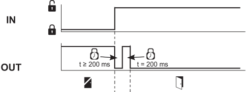

 | Lock |  | Unlock |  | Locking time |
 | Door open |  | Safety guard closed | ||
 | Safety guard not locked or fault |  | Safety guard locked |
6.5 Diagnostic information
| Table 1: Diagnostic information of the safety switchgear | |||||||
|---|---|---|---|---|---|---|---|
| System condition | Magnet control (bistable) IN | LED | Safety outputs Y1, Y2 | Diagnostic output OUT | |||
| green | red | yellow | AZM40Z | AZM40B | |||
| Door open | 24 V | On | Off | Off | 0 V | 0 V | 0 V |
| Door closed, not locked | 24 V | On | Off | Flashes | 0 V | 24 V | 24 V |
| Door closed, locking impossible | 0 V | On | Flashes 2) | Flashes | 0 V | 24 V | 0 V |
| Door closed and locked | 0 V | On | Off | On | 24 V | 24 V | 24 V |
| Error warning 1) | 0 V / 24 V | On | Flashes 2) | Flashes | 24 V / 0 V | 24 V1) | 0 V |
| Error | 0 V / 24 V | Flashes 2) | 0 V | 0 V | 0 V | ||
| Mechanical overload fault3) | 0 V | flashes synchronously | flashes synchronously | flashes synchronously | 0 V | 0 V | 0 V |
| Error in input circuit X1 and/or X2 | 0 V / 24 V | Flashes | Off | s. Section Diagnostic-LEDs | depending on the system status | ||
| Advance warning level Service life (95% Service life) | 0 V / 24 V | flashes synchronously | flashes synchronously | on / flashes / off | depending on the system status | ||
| Maximum service life achieved | 0 V / 24 V | flashes alternately | flashes alternately | Off | 0 V | 0 V | 0 V |
| Additionally for variant I1/I2: | |||||||
| Teach-in procedure actuator started | 24 V | Off | On | Flashes | 0 V | 0 V | 0 V |
| Only I2: teach-in procedure actuator (release block) | 24 V | Flashes | Off | Off | 0 V | 0 V | 0 V |
| 1) after 30 min: switch-off due to error 2) s. Flash code 3) In the event of complaints relating to the mechanical overload fault, the device including the associated actuator must always be sent in. | |||||||
| Table 2: Error messages / flash codes red diagnostic LED | |||
|---|---|---|---|
| Flash codes (red) | Designation | Autonomous switch-off after | Error cause |
| 1 flash pulse | Error (warning) at output Y1 | 30 min | Fault in output test or voltage at output Y1, although the output is disabled. |
| 2 flash pulses | Error (warning) at output Y2 | 30 min | Fault in output test or voltage at output Y2, although the output is disabled. |
| 3 flash pulses | Error (warning) cross-wire short | 30 min | Cross-wire short between the output cables or fault at both outputs |
| 4 flash pulses | Error (warning) temperature too high | 30 min | The temperature measurement reveals an internal temperature that is too high |
| 5 flash pulses | Actuator fault | 0 min | Incorrect or defective actuator |
| 6 flash pulses | Internal error | 0 min | Error at control inputs |
| 7 flash pulses | Error, interlock actuator | 0 min | Locking / unlocking blocked / incorrect position of manual release (at one of the two sides) |
| 8 flash pulses | Error (warning) over/under voltage | 30 min | Supply voltage outside specification |
| Continuous red | Internal error | 0 min | Device defective |
7 Set-up and maintenance
7.1 Functional testing
The safety function of the safety components must be tested. The following conditions must be previously checked and met:
- Fitting and integrity of the cable connections.
- Check the switch enclosure for damages
- Remove particles of dust and soiling.
7.2 Maintenance
In the case of correct installation and intended use, the safety switchgear is maintenance-free.
A regular visual inspection and functional test, including the following steps, is recommended:
- Check for a secure installation of the actuator and the solenoid interlock.
- Check max. misalignment of actuator unit and solenoid interlock and max. tipping and rotary angle and adjust using M4 socket head screws, if necessary.
- Fitting and integrity of the cable connections.
- Check the switch enclosure and actuator for damages.
- Remove particles of dust and soiling.
- Adequate measures must be taken to ensure protection against tampering either to prevent tampering of the safety guard, for instance by means of replacement actuators.
- Damaged or defective components must be replaced.
- After reaching a service life of 1,000,000 locking cycles or 500,000 actuator cycles (as of version "V2", see type plate), the solenoid interlock can no longer be locked and must be replaced, together with the actuator.
8 Disassembly and disposal
8.1 Disassembly
The safety switchgear must be disassembled in a de-energised condition only.
8.2 Disposal
- The safety switchgear must be disposed of in an appropriate manner in accordance with the national prescriptions and legislations.
Schmersal Canada Ltd., 29 Centennial Road, Unit 1, Orangeville, Ontario L9W 1R1 Canada
Les données et les valeurs ont été soigneusement vérifiées. Les illustrations peuvent être différentes de l'original. Vous trouverez d'avantage de caractéristiques techniques dans les manuels d’instructions. Sous réserve de modifications techniques et errata.
Généré le: 2024-06-02 22 h 57