RSS260-D-F0-LSTM12-8-0,25M
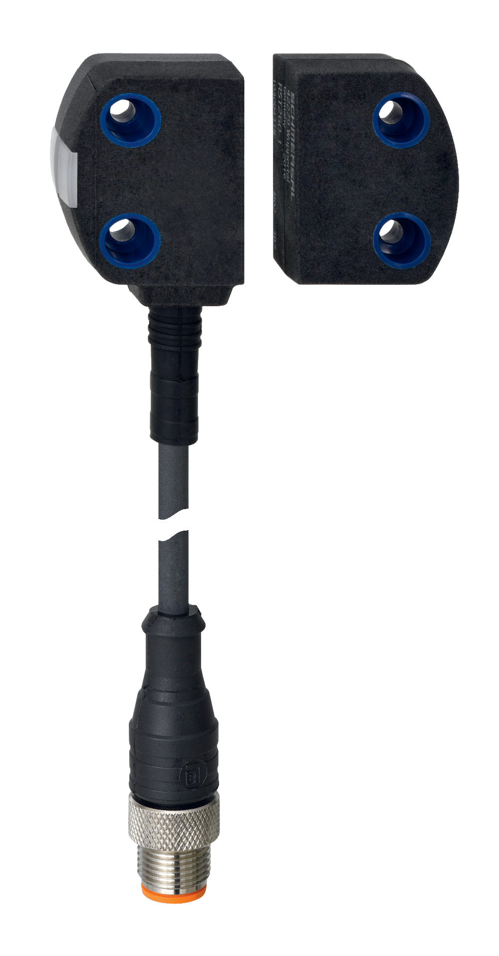
RSS260-D-F0-LSTM12-8-0,25M
| Désignation produit: RSS260-(1)-(2)-(3)-(4)-(5) |
| (1) | |
| Sans | Codage standard |
| I1 | Codage individuel |
| I2 | Codage individuel, apprentissage multiple |
| (2) | |
| D | Avec sortie diagnostique |
| SD | Avec sortie diagnostique via bus sériel 1) |
| (3) | |
| Sans | Version standard sans surveillance de la boucle de retour EDM (External Device Monitoring) |
| F0 | boucle de retour (EDM) avec réarmement automatique 1) |
| F1 | boucle de retour (EDM) avec réarmement manuel 1) |
| (4) | |
| Sans | sans arrêt d'urgence |
| Q | Acquittement après une erreur d'entrée par l'arrêt d'urgence 1) |
| (5) | |
| Sans | Câble de raccordement (Longueur en mètres) |
| ST | Connecteur intégré M8, 8 pôles |
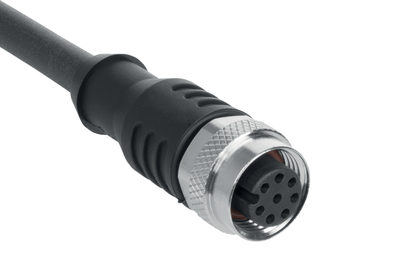
| LSTM12-8-0,25M | Câble de raccordement 0,25 m avec connecteur M12, 8 pôles |
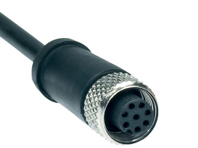
| LSTM8-8-0,1M | Câble de raccordement 0,1 m avec connecteur M8, 8 pôles |
| LSTM12-5-0,25M | Câble de raccordement 0,25 m avec connecteur M12, 5 pôles |
| (*) | |
| 1) | uniquement pour les versions -ST, -LSTM12-8-0,25M et -LSTM8-8-0,1M |
- Simple mounting without additional angle
- Universal coding with RFID technology
- Frontal and lateral actuation enabled
- RFID-technology for needs-based protection against tampering
- 8- pole cable connector M12
- Thermoplastic enclosure
Ordering data
| Product type description |
RSS260-D-F0-LSTM12-8-0,25M |
| Article number (order number) |
103040374 |
| EAN (European Article Number) |
4030661553757 |
| eCl@ss number, version 12.0 |
27-27-46-01 |
| eCl@ss number, version 11.0 |
27-27-24-03 |
| eCl@ss number, version 9.0 |
27-27-24-03 |
| ETIM number, version 7.0 |
EC001829 |
| ETIM number, version 6.0 |
EC001829 |
Approvals - Standards
| Certificates |
TÜV cULus FCC IC ANATEL |
General data
| Standards |
EN ISO 13849-1 EN IEC 60947-5-3 EN IEC 61508 |
| Coding |
Codage universel |
| Coding level according to EN ISO 14119 |
faible |
| Working principle |
RFID |
| Frequency band RFID |
125 kHz |
| Transmitter output RFID, maximum |
-6 dB/m |
| Housing construction form |
Bloc |
| Installation conditions (mechanical) |
non affleuré |
| Sensor topology |
Connexion en série |
| Housing material |
Plastique, thermoplastique, auto-extinguible |
| Active area |
Plastique, thermoplastique |
| Reaction time, maximum |
100 ms |
| Duration of risk, maximum |
200 ms |
| Reaction time, switching off safety outputs via actuator, maximum |
100 ms |
| Gross weight |
80 g |
General data - Features
| Diagnostic output |
Oui |
| Short circuit detection |
Oui |
| Cross-circuit detection |
Oui |
| Series-wiring |
Oui |
| Safety functions |
Oui |
| Cascadable |
Oui |
| Feedback circuit |
Oui |
| Automatic reset function |
Oui |
| Integral system diagnostics, status |
Oui |
| Number of LEDs |
3 |
| Number of semi-conductor outputs with signaling function |
1 |
| Number of poles |
8 |
| Number of fail-safe digital outputs |
2 |
| Safety classification |
| Vorschriften |
EN ISO 13849-1 EN IEC 61508 |
| Performance Level, up to |
e |
| Category |
4 |
| PFH value |
6,80 x 10⁻¹⁰ /h |
| PFD value |
1,20 x 10⁻⁴ |
| Safety Integrity Level (SIL), suitable for applications in |
3 |
| Mission time |
20 Year(s) |
Mechanical data
| Actuating panels |
latéral côté avant |
| Active area |
latéral avant |
| Mounting |
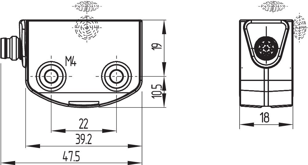
Pour le montage des capteurs, des vis longues de 20 mm conviennent de façon générale. Lorsque les plaques de montage sont utilisées, des vis longues de 25 mm sont recommandées. |
| Type of the fixing screws |
2x M4 |
| Tightening torque of the fixing screws, maximum |
0,8 Nm |
Mechanical data - Switching distances
| Typical switching distance, frontal |
12 mm |
| Typical switching distance, lateral |
9 mm |
| Assured switching distance "ON", frontal |
10 mm |
| Assured switching distance "OFF", frontal |
18 mm |
| Assured switching distance "ON", lateral |
6 mm |
| Assured switching distance "OFF", lateral |
15 mm |
| Note (Sao) |
The specifications of the safety switching distance Sao refer to a temperature range of |
| Note (switching distance) |
All switching distances in accordance EN IEC 60947-5-3 Décalage axial, un désalignement horizontal et vertical est toléré entre le capteur de sécurité et l'actionneur. Le désalignement dépend de la distance entre le capteur et l'actionneur. Le capteur est activé dans la limite de tolérance. |
| Hysteresis (Switching distance), maximum |
2 mm |
| Repeat accuracy R |
0,5 mm |
| Note (Repeat accuracy R) |
Décalage latéral: le côté long permet un décalage en hauteur max. (x) entre le capteur et l'actionneur de 8 mm (p.ex. suite aux erreurs de montage ou au désalignement du protecteur). Le décalage transversal (y) s'élève à max. ± 18 mm (voir dessin: principe de fonctionnement).Distance min. entre deux systèmes de capteur 100 mm |
Mechanical data - Connection technique
| Note (length of the sensor chain) |
Cable length and cross-section change the voltage drop dependiing on the output current |
| Note (series-wiring) |
Unlimited number of devices, oberserve external line fusing, max. 31 devices in case of serial diagnostic SD |
| Termination |
Connecteur M12, 8 pôles, codage A |
Mechanical data - Dimensions
| Length of sensor |
29,5 mm |
| Width of sensor |
39,2 mm |
| Height of sensor |
18 mm |
Ambient conditions
| Degree of protection |
IP65 IP67 |
| Ambient temperature |
-28 ... +65 °C |
| Storage and transport temperature |
-28 ... +85 °C |
| Relative humidity, maximum |
93 % |
| Note (Relative humidity) |
sans condensation non givrant |
| Resistance to vibrations |
10…55 Hz, amplitude 1 mm |
| Restistance to shock |
30 g / 11 ms |
| Permissible installation altitude above sea level, maximum |
2 000 m |
Ambient conditions - Insulation values
| Rated insulation voltage Ui |
32 VDC |
| Rated impulse withstand voltage Uimp |
0,8 kV |
| Overvoltage category |
III |
| Degree of pollution |
3 |
Electrical data
| Operating voltage |
24 VDC -15 % / +10 % |
| Operating current, minimum |
0,5 mA |
| No-load supply current I0, typical |
35 mA |
| Rated operating voltage |
24 VDC |
| Operating current |
600 mA |
| Required rated short-circuit current |
100 A |
| Time to readiness, maximum |
2 000 ms |
| Switching frequency, maximum |
1 Hz |
| Utilisation category DC-12 |
24 VDC / 0,05 A |
| Electrical fuse rating, maximum |
2 A |
Electrical data - Safety digital inputs
| Designation, Safety inputs |
X1 and X2 |
| Current consumption of the safety inputs |
5 mA |
| Test pulse duration, maximum |
1 ms |
| Test pulse interval, minimum |
100 ms |
| Classification ZVEI CB24I, Sink |
C1 |
| Classification ZVEI CB24I, Source |
C1 C2 C3 |
Electrical data - Safety digital outputs
| Designation, Safety outputs |
Y1 et Y2 |
| Rated operating current (safety outputs) |
250 mA |
| Output current, (fail-safe output), maximum |
0,25 A |
| Design of control elements |
protégé contre les courts-circuits, commutation P |
| Voltage drop Ud, maximum |
1 V |
| Leakage current Ir, maximum |
0,5 mA |
| Voltage, Utilisation category DC-12 |
24 VDC |
| Current, Utilisation category DC-12 |
0,25 A |
| Voltage, Utilisation category DC-13 |
24 VDC |
| Current, Utilisation category DC-13 |
0,25 A |
| Test pulse interval, typical |
1000 ms |
| Test pulse duration, maximum |
1 ms |
| Classification ZVEI CB24I, Source |
C2 |
| Classification ZVEI CB24I, Sink |
C1 C2 |
Electrical data - Diagnostic outputs
| Designation, Diagnostic outputs |
OUT |
| Operating current |
50 mA |
| Voltage drop Ud, maximum |
2 V |
| Voltage, Utilisation category DC-12 |
24 VDC |
| Current, Utilisation category DC-12 |
0,05 A |
| Voltage, Utilisation category DC-13 |
24 VDC |
| Current, Utilisation category DC-13 |
0,05 A |
Electrical data - Electromagnetic compatibility (EMC)
| Interfering radiation |
IEC 61000-6-4 |
Status indication
| Note (LED switching conditions display) |
LED jaune: état de fonctionnement LED verte: tension d'alimentation LED rouge: défaut |
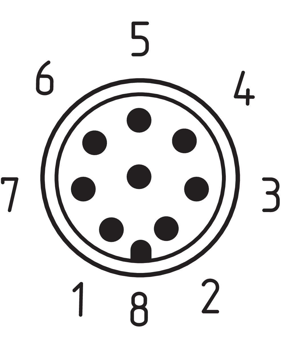
Pin assignment
| PIN 1 |
A1 Tension d'alimentation UB |
| PIN 2 |
X1 Entrée de sécurité 1 |
| PIN 3 |
A2 GND |
| PIN 4 |
Y1 Sortie de sécurité 1 |
| PIN 5 |
OUT Sortie diagnostic "OUT" |
| PIN 6 |
X2 Entrée de sécurité 2 |
| PIN 7 |
Y2 Sortie de sécurité 2 |
| PIN 8 |
sans fonction |
Scope of delivery
| Scope of delivery |
Actuator must be ordered separately. |
Accessory
| Recommendation (actuator) |
RST16-1 RST-U-2 RST260-1 |
Filtre de langue
Fiches techniques
Mode d'emploi et déclaration de conformité
Certification ANATEL
Certificat UL
FCC-Zertifikat
IC-Zertifikat
Homologation TÜV
Brochure
Bibliothèque/Library SISTEMA-VDMA
Télécharger la dernière version d'Adobe Reader
Photo du produit (photo individuelle de catalogue)
Plan d'encombrement composant de base
Video ID: RSS-260-12
RST-U-2 actuator for confined spaces (Vimeo)

Video ID: RSS260-13
Produktinformation RSS260 (Vimeo)
Video ID: RSS-260-01
Basic function (Vimeo)
Video ID: RSS-260-02
Variable mounting options (Vimeo)
Video ID: RSS-260-03
Single device connection (Vimeo)
Video ID: RSS-260-04
Series connection with serial diagnostics (Vimeo)
Video ID: RSS-260-05
Cross-fault with controlled shut-down process (Vimeo)
Video ID: RSS-260-06
Tolerance to misalignment (Vimeo)
Video ID: RSS-260-07
Warning when actuator is in limit range (Vimeo)
Video ID: RSS-260-11
RST-16-1 actuator on flat contour safety guards (Vimeo)

103009970 SRB-E-201LC
- Plug-in screw terminals with coding
- STOP 0 Function
- 1 oder 2-channel control
- Start button / Auto-start
- 2 Safety outputs 2 A
- 1 Signalling output

103009973 SRB-E-204ST
- Plug-in screw terminals with coding
- STOP 0 Function
- Monitoring of 4 sensors
- Start button / Auto-start
- 2 Safety outputs
- 4 Signalling outputs

103007672 SRB-E-301ST
- Plug-in screw terminals with coding
- STOP 0 Function
- 1 oder 2-channel control
- Start button / Auto-start
- 1 Auxiliary contact
- 3 safety contacts
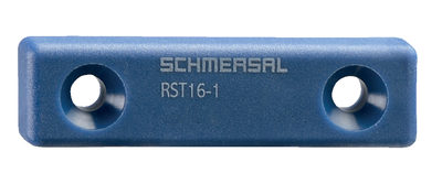
103004336 RST16-1
- Frontal actuation from assembly direction
- Flat design
- Mounting 2 x M5
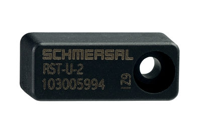
103005994 RST-U-2
- Frontal actuation from assembly direction
- small body
- Mounting 1 x M3 plus Twist protection
103004318 RST260-1
- Actuation from side
- Simple mounting
- Mounting 2 x M4
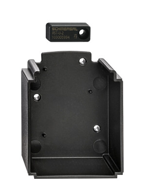
103055438 ACC-DHS-U1-INS-RST-U-2
- Actuator insert
- Incl. RST-U-2 actuator and attachment screw
- For use of the DHS-U1 in conjunction with safety sensor RSS260

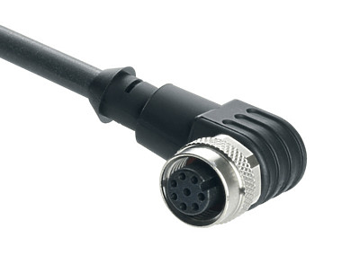
103043110 A-K8P-M12-S-W-2,5M-BK-2-X-A-4
- angled
- 2.5 m
- Pre-wired cable
- 8-pole
103043119 A-K8P-M12-S-W-5M-BK-2-X-A-4
- angled
- 5 m
- Pre-wired cable
- 8-pole
103043120 A-K8P-M12-S-W-10M-BK-2-X-A-4
- angled
- 10 m
- Pre-wired cable
- 8-pole
103043121 A-K8P-M12-S-W-15M-BK-2-X-A-4
- angled
- 15
- Pre-wired cable
- 8-pole
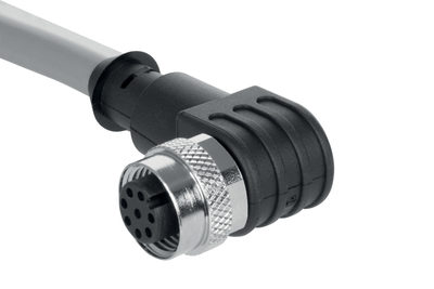
103011416 A-K8P-M12-S-W-5M-GY-1-X-A-4
- 5 m
- Pre-wired cable
- 8-pole
101210561 A-K8P-M12-S-W-5M-BK-1-X-A-4-69-VA
- 5 m
- angled
- Pre-wired cable
- 8-pole
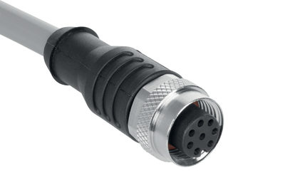
103011412 A-K8P-M12-S-G-5M-GY-1-X-A-4
- 5.0
- Pre-wired cable
- 8-pole
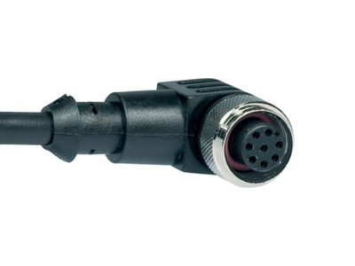
103007358 A-K8P-M12-S-G-5M-BK-2-X-A-4-69
- 5 m
- Pre-wired cable
- 8-pole
101210560 A-K8P-M12-S-G-5M-BK-1-X-A-4-69-VA
- 5 m
- Pre-wired cable
- 8-pole
103011411 A-K8P-M12-S-G-2,5M-GY-1-X-A-4
- 2.5 m
- Pre-wired cable
- 8-pole
103011415 A-K8P-M12-S-G-2.5M-BK-2-X-A-4-69
- 2.5 m
- Pre-wired cable
- 8-pole
103011414 A-K8P-M12-S-G-15M-BK-2-X-A-4-69
- 15
- Pre-wired cable
- 8-pole
103014823 A-K8P-M12-S-G-15M-BK-1-X-A-4-69-VA
- 15
- Pre-wired cable
- 8-pole
103011413 A-K8P-M12-S-G-10M-GY-1-X-A-4
- 10 m
- Pre-wired cable
- 8-pole
103007359 A-K8P-M12-S-G-10M-BK-2-X-A-4-69
- 10 m
- Pre-wired cable
- 8-pole
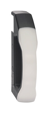
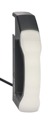
103053675 DHS-U1-BKWH
- Without electrical connection
- Door handle in an ergonomical design
- Can be combined with solenoid interlock AZM40 or safety sensor RSS260
- Can also be used without safety switchgear device
- For left or right hinged safety guards
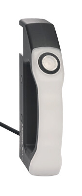
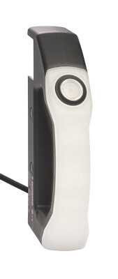
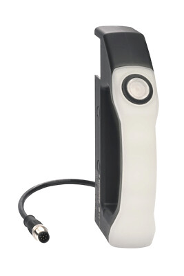
103053688 DHS-U1-BKWH-L5-5.00-LT
- With illuminated pushbutton
- Connecting cable, 5-core, 5 m
- Protection class IP65 / IP67
- Machine status directly recognisable on the door handle
- Door handle in an ergonomical design
- Can be combined with solenoid interlock AZM40 or safety sensor RSS260
- Can also be used without safety switchgear device
- For left or right hinged safety guards
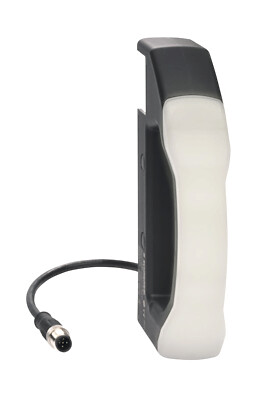
103053692 DHS-U1-BKWH-L5-5.00-RGB
- Connecting cable, 5-core, 5 m
- Degree of protection IP65 / IP67
- Machine status directly recognisable on the door handle
- With door handle lighting
- Door handle in an ergonomical design
- Can be combined with solenoid interlock AZM40 or safety sensor RSS260
- Can also be used without safety switchgear device
- For left or right hinged safety guards
103053689 DHS-U1-BKWH-L8-5.00-RGB-LT
- For left or right hinged safety guards
- With door handle lighting and illuminated push-button
- Connecting cable, 8-core, 5 m
- Protection class IP65 / IP67
- Machine status directly recognisable on the door handle
- Door handle in an ergonomical design
- Can be combined with solenoid interlock AZM40 or safety sensor RSS260
- Can also be used without safety switchgear device
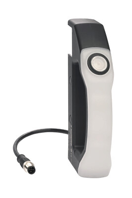
103053676 DHS-U1-BKWH-LST5-0.25-LT
- With illuminated pushbutton
- Connecting cable with connector M12, 5-pole, 0.25 m
- Protection class IP65 / IP67
- Machine status directly recognisable on the door handle
- Door handle in an ergonomical design
- Can be combined with solenoid interlock AZM40 or safety sensor RSS260
- Can also be used without safety switchgear device
- For left or right hinged safety guards
103053691 DHS-U1-BKWH-LST5-0.25-RGB
- With door handle lighting
- Connecting cable with connector M12, 5-pole, 0.25 m
- Degree of protection IP65 / IP67
- Machine status directly recognisable on the door handle
- Door handle in an ergonomical design
- Can be combined with solenoid interlock AZM40 or safety sensor RSS260
- Can also be used without safety switchgear device
- For left or right hinged safety guards
103053677 DHS-U1-BKWH-LST8-0.25-RGB-LT
- With door handle lighting and illuminated push-button
- Connecting cable with connector M12, 8-pole, 0.25 m
- Protection class IP65 / IP67
- Machine status directly recognisable on the door handle
- Door handle in an ergonomical design
- Can be combined with solenoid interlock AZM40 or safety sensor RSS260
- Can also be used without safety switchgear device
- For left or right hinged safety guards
| EU Declaration of Conformity |  |
| Original | K.A. Schmersal GmbH & Co. KG Möddinghofe 30 42279 Wuppertal Germany Internet: www.schmersal.com |
| Declaration: | We hereby certify that the hereafter described components both in their basic design and construction conform to the applicable European Directives. |
| Name of the component: | RSS260 |
| Type: | See ordering code |
| Description of the component: | Non-contact safety sensor |
| Relevant Directives: | Machinery Directive | 2006/42/EC |
| RED-Directive | 2014/53/EU | |
| RoHS-Directive | 2011/65/EU |
| Applied standards: | EN 60947-5-3:2013 EN 300 330 V2.1.1:2017 EN ISO 14119:2013 EN ISO 13849-1:2023 EN 61508 parts 1-7:2010 |
| Notified body for Type Examination: | TÜV Rheinland Industrie Service GmbH Am Grauen Stein, 51105 Köln ID n°: 0035 |
| EC-Type Examination Certificate: | 01/205/5348.04/25 |
| Person authorised for the compilation of the technical documentation: | Oliver Wacker Möddinghofe 30 42279 Wuppertal |
| Place and date of issue: | Wuppertal, January 9, 2025 |
 |
| Authorised signature Philip Schmersal Managing Director |
| UK Declaration of Conformity | |
| Company: | K.A. Schmersal GmbH & Co. KG Möddinghofe 30 42279 Wuppertal Germany Internet: www.schmersal.com |
| Declaration: | We hereby, under sole responsibility, certify that the hereafter described components both in their basic design and construction conform to the relevant statutory requirements, regulations and designated standards of the United Kingdom. |
| Name of the component: | RSS260 |
| Type: | See ordering code |
| Description of the component: | Non-contact safety sensor |
| Relevant legislation: | Supply of Machinery (Safety) Regulations | 2008 |
| Radio Equipment Regulations | 2017 | |
| The Restriction of the Use of Certain Hazardous Substances in Electrical and Electronic Equipment Regulations | 2012 |
| Designated standards: | EN 60947-5-3:2013 EN 300 330 V2.1.1:2017 EN ISO 14119:2013 EN ISO 13849-1:2015 IEC 61508 parts 1-7:2010 |
| Approved body for Type Examination: | TÜV Rheinland UK Ltd. 1011 Stratford Road Solihull, B90 4BN ID: 2571 |
| Type examination certificate: | 01/205U/5348.00/22 |
| UK-Importer / Person authorised for the compilation of the technical documentation: | Schmersal UK Ltd. Paul Kenney Unit 1, Sparrowhawk Close Enigma Business Park Malvern, Worcestershire, WR14 1GL |
| Place and date of issue: | Wuppertal, November 2, 2022 |
|
| Authorised signature Philip Schmersal Managing Director |
Schmersal India Pvt. Ltd., Plot No - G-7/1, Ranjangaon MIDC, Tal. - Shirur, Dist.- Pune 412 220
Les données et les valeurs ont été soigneusement vérifiées. Les illustrations peuvent être différentes de l'original. Vous trouverez d'avantage de caractéristiques techniques dans les manuels d’instructions. Sous réserve de modifications techniques et errata.
Généré le: 01/05/2025 07:14