BN 12-10Z
BN 12-10Z
Downloads
- サイドオンタイプ
- プル・ワイヤー・ケーブル付
- バイアスマグネット付き
- 非接触式
- 長寿命
- 金属製エンクロージャ
- 動作マグネットと仕様により、動作距離は60mmまで
- 設計 Ø 10,7 mm
- 中央取り付け
注文データ
| 製品タイプの説明 |
BN 12-10Z |
| 部品番号(注文番号) |
101101263 |
| EAN(欧州部品番号) |
4030661335315 |
| eCl@ss番号、バージョン12.0 |
27-27-43-02 |
| eCl@ss番号、バージョン11.0 |
27-27-01-05 |
| eCl@ss番号、バージョン9.0 |
27-27-01-05 |
| ETIM番号、バージョン7.0 |
EC002544 |
| ETIM番号、バージョン6.0 |
EC002544 |
一般データ
| アクティブ原理 |
磁気装置 |
| ハウジング形状 |
シリンダー型、ネジ式 |
| ハウジング 材質 |
金属フィルム |
| 総重量 |
60 g |
一般データ - 仕様
| エレベーターに最適 |
Yes |
| バイアス磁石 |
Yes |
| NO接点の数 |
1 |
機械的データ
| 作動範囲 |
側面 |
| 動作エレメント |
ソレノイド |
| 機械的寿命、最小 |
10,000,000 操作 |
| 作動速度, 最大 |
18 m/s |
| 取り付け |
中央にネジ付きフランジM12 x 1 |
Mechanical data - Switching distances
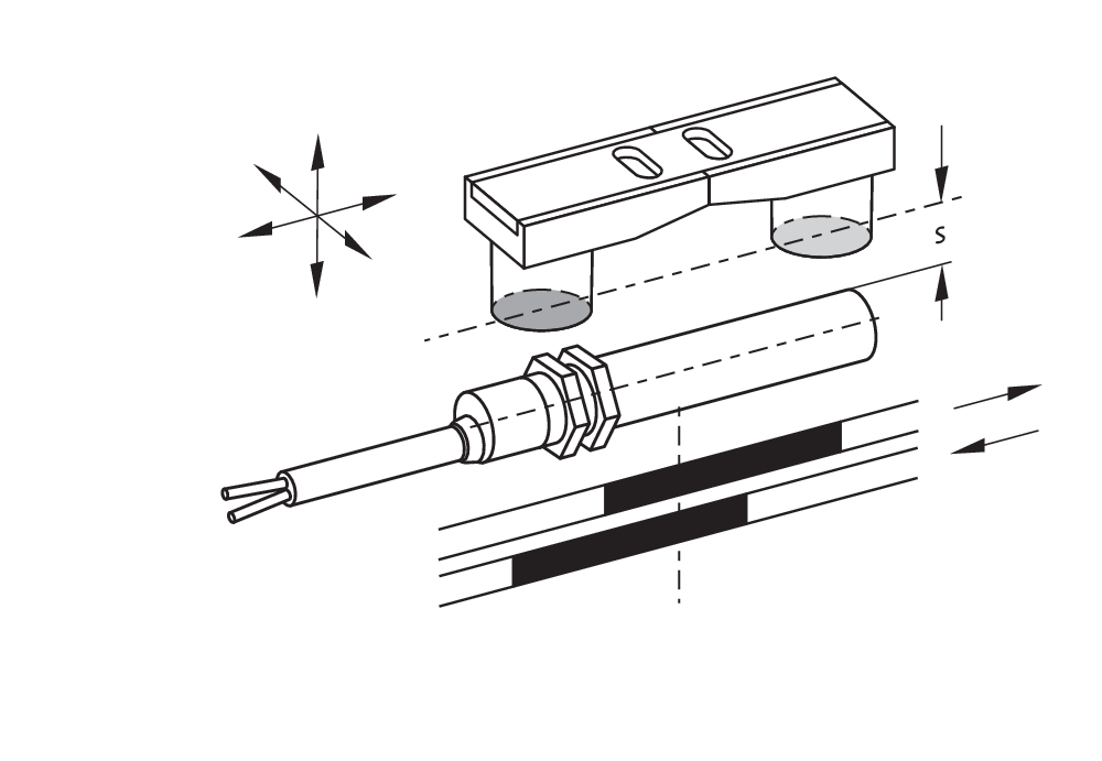
| 動作距離 Sn |
5 mm … 50 mm BP 10 = 5 mm 2 x BP 10 = 17 mm BP 15 = 6 mm 2 x BP 15 = 17 mm 2 x BP 15/2 = 17 mm BP 34 = 15 ... 20 mm BP 20 = 20 mm BP 31 = 20 mm BP 11 = 20 mm BP 12 = 10 ... 30 mm BP 21 = 25 ... 50 mm |
| 注記 (動作距離 Sn) |
Actuating distance up to 50 mm depending on actuating magnet and version. The specified switching distances are applicable for the actuation of individually mounted components without ferromagnetic influence. A change of the distance, either positive or negative, is possible due to ferromagnetic influences. The mutual interference between multiple actuating magnets must be observed. |
| 注記 (動作距離) |
All switching distances in accordance EN IEC 60947-5-2 |
| 切換位置再現性 R |
0.3 mm |
機械的データ - 電気機械式
| ケーブルの長さ |
1 m |
| 接続 |
既配線ケーブル |
| ケーブルワイヤーの数 |
2 |
| ワイヤー断面積 |
0.25 mm2 |
| ワイヤー断面積 |
23 AWG |
| ケーブルマントルの材質 |
PVC |
| ケーブルタイプ |
LiYY |
機械的データ - 寸法
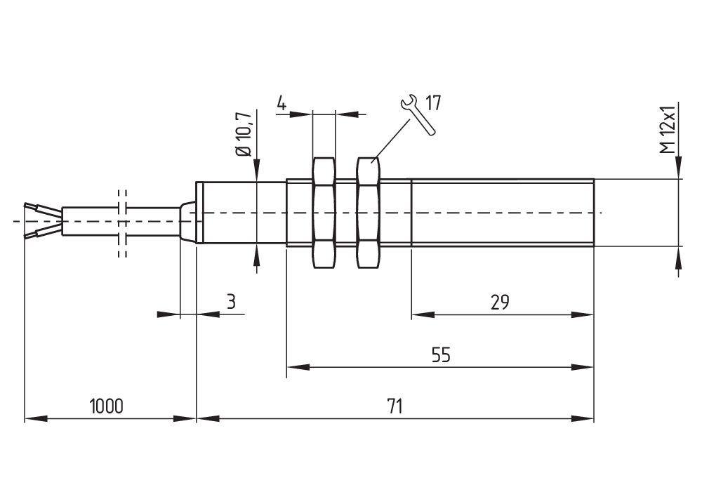
| センサーの直径 |
10.7 mm |
| センサー長 |
71 mm |
環境条件
| 保護等級 |
IP67 |
| 使用周囲温度 |
-25 ... +70 °C |
| 耐振動 |
10 ~ 55 Hz, 振幅 1 mm |
| 耐衝撃 |
30 g / 11 ms |
電気的データ
| 開閉電圧、最大 |
200 VAC |
| スイッチング電流, 最大 |
1 A |
| 開閉容量、最大 |
30 W |
| 開閉容量、最大 |
30 VA |
| スイッチ原理 |
リード接点、非接触原理 |
| バウンス時間、最大 |
0.2 ms |
| 開閉頻度、最大 |
300 Hz |
| スイッチ素子 |
NO接点 |
納入品目
| 納入時同梱 |
Actuator must be ordered separately. |
アクセサリー
| 推奨(アクチュエーター) |
BP 10 2x BP 10 BP 15 2x BP 15 2x BP 15/2 BP 34 BP 20 BP 31 BP 11 BP 12 BP 21 |
| 推奨 (アクチュエータ、エレベーター用スイッチ) |
BP 10 2 x BP 15/2 2 x BP 15 2 x BP 10 BP 15 BP 34 |
Note
| 注記 (一般) |
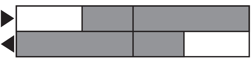
The opening and closing functions depend on the direction of actuation, the actuating magnets and the polarity of the actuating magnets. When the switches and actuators come together, the colours must coincide: Red (S) to red (S) and green (N) to green (N). This does not apply to the bistable contact. The switch is to be mounted on iron with a non-magnetic layer of at least 20 mm. |
言語フィルター
データシート
Mounting and wiring instructions
EC Declaration of conformity
Info
Adobe Readerの最新版をダウンロードしてください
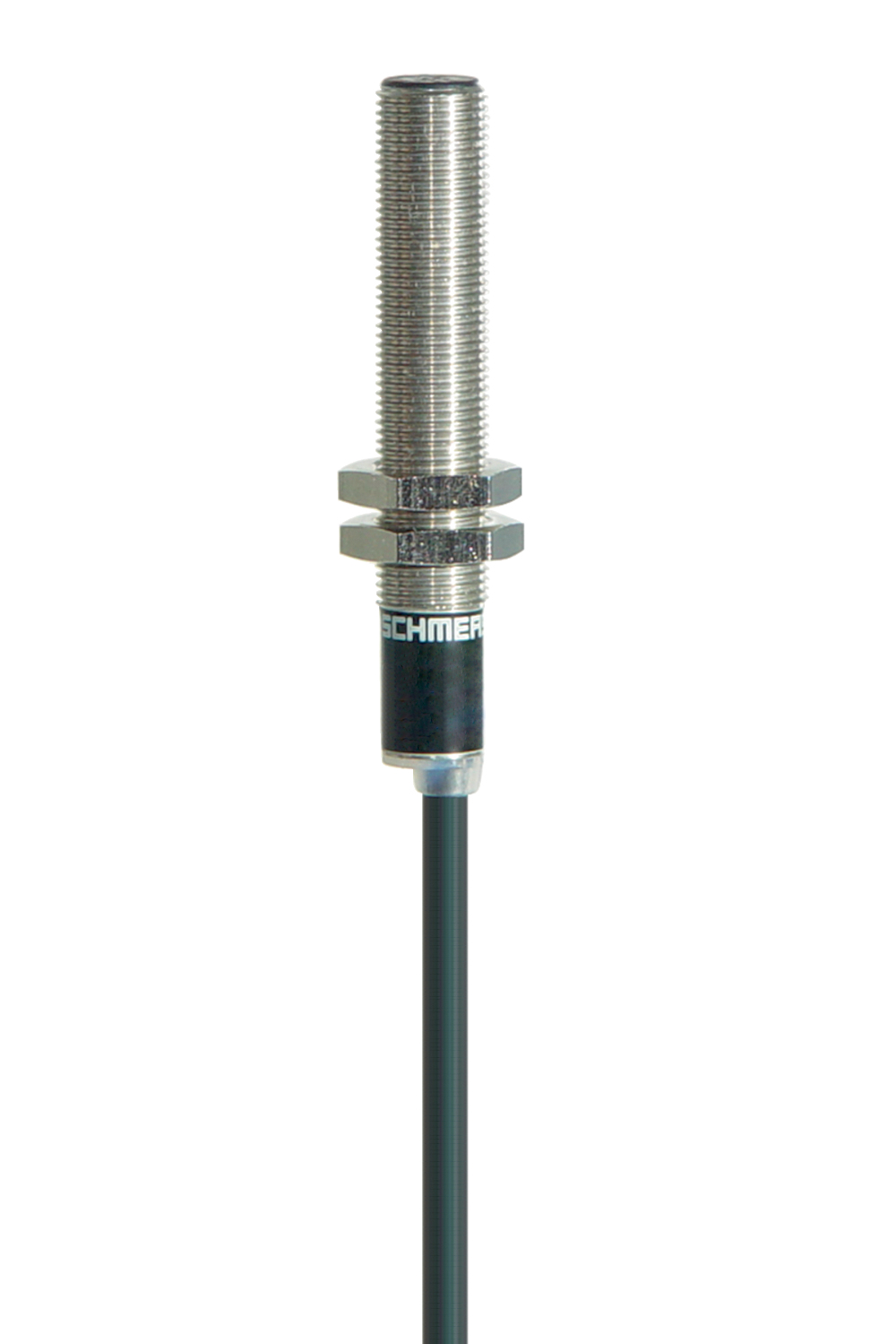
Product picture (catalogue individual photo)
Dimensional drawing basic component
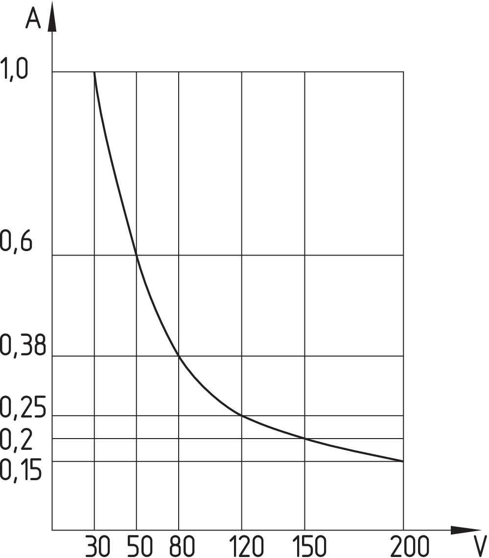
Switch travel diagram
Diagram
Characteristic curve
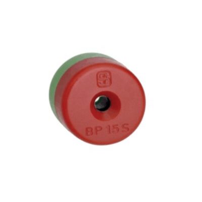
101060163 BP 15
- プラスティック製カバー
- N極は緑色で表示されています。
- S芯赤表示
- 鉄上に18mm距離で取り付け可
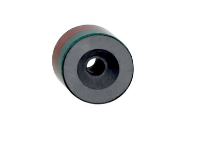
101060165 BP 15/2
- ケース無し
- 極性が圧縮されています。
- 鉄上に18mm距離で取り付け可
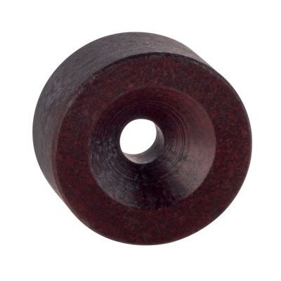
101057531 BP 10
- ケース無し
- 貼付フィルムによる両芯の色表示
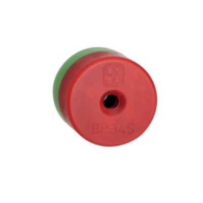
151057553 BP34
- プラスティック製カバー
- S芯赤表示
- N極は緑色で表示されています。
- 鉄上に25mm距離で取り付け可
シュメアザール株式会社, 〒222-0033 横浜市港北区新横浜3-9-5, 新横浜第3東昇ビル
データと詳細は完全にチェックされました。画像は元の画像と異なる場合があります。技術的なデータはマニュアルで見られます。技術的に変更されたり、エラーの可能性があります。
Generated on 2025/10/21 19:34