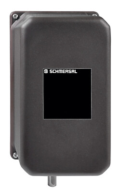
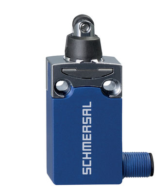
FWS 1206 A

- 1つまたは2つのインパルスセンサ付静状況検出
- 第二の入力チャンネルとしてのPLCなど追加停止信号の使用
- 2 安全出力
- 2 補助出力
注文データ
| 注記 (配信容量) |
Not available! |
| 製品タイプの説明 |
FWS 1206 A |
| 部品番号(注文番号) |
101170057 |
| EAN(欧州部品番号) |
4030661297194 |
| eCl@ss番号、バージョン12.0 |
27-37-18-19 |
| eCl@ss番号、バージョン11.0 |
27-37-18-19 |
| eCl@ss番号、バージョン9.0 |
27-37-18-19 |
| ETIM番号、バージョン7.0 |
EC001449 |
| ETIM番号、バージョン6.0 |
EC001449 |
| まで入手可能 |
31.12.2024 |
認証
|
cULus |
一般データ
| 規格 |
BG-GS-ET-20 EN IEC 62061 EN ISO 13849-1 EN IEC 60947-5-1 EN IEC 60947-5-3 EN IEC 60947-5-5 EN IEC 60204-1 EN IEC 60947-1 |
| 環境ストレス |
EN 60068-2-3 BG-GS-ET-14 |
| ハウジング 材質 |
グラスファイバー強化熱可塑性樹脂、換気口付き |
| 総重量 |
200 g |
一般データ - 仕様
| 断線検出 |
Yes |
| バックチェック回路 |
Yes |
| 立ち下がり検出でリセット |
Yes |
| 地絡検出 |
Yes |
| 一体型システム診断、状態 |
Yes |
| LEDの数 |
1 |
| 数、信号機能付き遅延のない半導体出力の数 |
2 |
| 安全接点数 |
2 |
| 信号出力数 |
2 |
安全性評価
| 規定 |
EN IEC 61508 |
| パフォーマンスレベル、最大 |
d |
| カテゴリー |
3 |
| PFH値 |
1.00 x 10⁻⁷ /h |
| 安全インテグリティレベル (SIL), 安全度水準に適合 |
2 |
| ミッションタイム |
20 年 |
| 停止カテゴリー |
0 |
機械的データ
| 機械的寿命、最小 |
20,000,000 操作 |
| 取り付け |
EN 60715に基づくDINレールにワンタッチ取り付け |
機械的データ - 電気機械式
| 配線表示 |
IEC/EN 60947-1 |
| 接続 |
単線 / 撚線 ネジ端子 M20 x 1.5 |
| ケーブル断面積、最小 |
0.2 mm² |
| ケーブル断面積, 最大 |
2.5 mm² |
| クリップの締付トルク |
0.6 Nm |
機械的データ - 寸法
| 幅 |
22.5 mm |
| 高さ |
100 mm |
| 深さ |
121 mm |
環境条件
| ハウジングの保護等級 |
IP40 |
| 取付領域の保護等級 |
IP54 |
| クリップまたは端子の保護等級 |
IP20 |
| 使用周囲温度 |
+0 ... +55 °C |
| 保管および輸送温度 |
-25 ... +70 °C |
| 耐振動 |
10 ~ 55 Hz、振幅 0.35 mm |
| 耐衝撃 |
30 g / 11 ms |
環境条件 - 絶縁値
| 定格インパルス耐電圧 Uimp |
4.8 kV |
| 過電圧カテゴリー |
II |
| 汚染度 |
3 |
電気的データ
| 動作電圧 |
24 VDC -15 % / +15 % |
| 熱試験電流 |
6 A |
| 定格動作電圧 |
24 VDC |
| 制御用定格AC電圧、50 Hz、最小 |
20.4 VAC |
| 定格制御電圧 AC 50 Hzにて、最大 |
26.4 VAC |
| 制御用定格AC電圧、60 Hz、最小 |
20.4 VAC |
| 定格制御電圧 AC 60 Hzにて、最大 |
26.4 VAC |
| DC最小で制御するための定格AC電圧 |
20.4 VDC |
| 定格制御電圧 DCにて、最大 |
28.8 VDC |
| 消費電力、最大 |
5 W |
| 接点抵抗, 最大 |
0.1 Ω |
| 注意(接点抵抗) |
新しい状態で |
| 接点材質、電気的 |
Ag-Ni 10および0.2 µm 金メッキ |
電気的データ - 安全リレー出力
| 電圧, 使用カテゴリー AC-15 |
230 VAC |
| 電流、使用カテゴリー AC-15 |
3 A |
| 電圧, 使用カテゴリー DC-13 |
24 VDC |
| 電流、使用カテゴリーDC-13 |
2 A |
| 開閉容量、最小 |
10 VDC |
| 開閉容量、最小 |
10 mA |
| 開閉容量、最大 |
250 VAC |
| 開閉容量、最大 |
8 A |
電気的データ - デジタル入力
| 入力信号, HIGH信号 "1" |
10 … 30 VDC |
| 入力信号、LOW信号 "0" |
0 … 2 VDC |
| 配線抵抗, 最大 |
40 Ω |
電気的データ - リレー出力 (補助接点)
| 開閉容量、最大 |
24 VDC |
| 開閉容量、最大 |
2 A |
Integral system diagnosis (ISD)
| 注記 (ISD -故障) |
The following faults are registered by the safety monitoring modules and indicated by ISD. |
| 故障 |
Failure of the safety relay to pull-in or drop-out Fault on the input circuits or the relay control circuits of the safety monitoring module Failure of the proximity switches Failure of one channel being evaluated Interruption of the connections to the inductive proximity switches |
その他のデータ
| 注意 (アプリケーション) |
安全な静止監視 |
Note
| 注記 (一般) |
Inductive loads (e.g. contactors, relays, etc.) are to be suppressed by means of a suitable circuit. |
回路例
| 注記 (配線図) |
The wiring diagram is shown with guard doors closed and in de-energised condition. The ISD tables (Intergral System Diagnostics) for analysis of the fault indications and their causes are shown in the appendix. To monitor one guard door at plants with dangerous run-on movements up to PL d and Category 3 Standstill monitoring for unlocking solenoid interlocks For suitable IFL range p-type inductive proximity switches, refer to "Schmersal Catalogue Automatisierungstechnik". The solenoid interlock can be opened, when the standstill monitor has detected the end of the run-on movement by means of one or two inductive proximity switches as well as the supplementary standstill signal (H7). When the button (E) is actuated, the coil of the solenoid interlock is energised. |
言語フィルター
データシート
Operating instructions and Declaration of conformity
UL Certificate
Info
Wiring example (electr. wiring)
SISTEMA-VDMA library
Adobe Readerの最新版をダウンロードしてください
Product picture (catalogue individual photo)
Wiring example

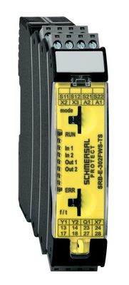
103014754 SRB-E-302FWS-TS
- 2 安全接点, 1 安全出力
- 1つまたは2つのインパルスセンサ付静状況検出
- 追加の静止信号、例えば2番目の入力チャネルとしてのPLC
- 2チャンネル時間監視
| EU Declaration of Conformity |  |
| Original | K.A. Schmersal GmbH & Co. KG Möddinghofe 30 42279 Wuppertal Germany Internet: www.schmersal.com |
| Declaration: | We hereby certify that the hereafter described components both in their basic design and construction conform to the applicable European Directives. |
| Name of the component: | FWS 1206 |
| Type: | See ordering code |
| Description of the component: | Fail-safe standstill monitor |
| Relevant Directives: | Machinery Directive | 2006/42/EC |
| EMC-Directive | 2014/30/EU | |
| RoHS-Directive | 2011/65/EU |
| Applied standards: | EN 60947-5-1:2017 + AC:2020 EN ISO 13849-1: 2015 EN ISO 13849-2: 2012 |
| Notified body, which approved the full quality assurance system, referred to in Appendix X, 2006/42/EC: | TÜV Rheinland Industrie Service GmbH Am Grauen Stein, 51105 Köln ID n°: 0035 |
| Person authorised for the compilation of the technical documentation: | Oliver Wacker Möddinghofe 30 42279 Wuppertal |
| Place and date of issue: | Wuppertal, August 4, 2023 |
 |
| Authorised signature Philip Schmersal Managing Director |
シュメアザー株式会社, 〒222-0033 横浜市港北区新横浜3-9-5, 新横浜第3東昇ビル
データと詳細は完全にチェックされました。画像は元の画像と異なる場合があります。技術的なデータはマニュアルで見られます。技術的に変更されたり、エラーの可能性があります。
Generated on 2025/09/10 16:03
最近見た製品
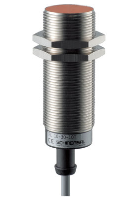
IFL 10-30-10STP
G50-025M44/44Y-1600-1-1368-3
PS116-Z02-STR-R200
SHGV/R01/120+BO