AZM 161CC-12/12RKED/TU -024

| 产品描述: AZM161 (1)-(2)(3)K(4)-(5)/(6)-(7)(8) |
| (1) | |
| SK | 螺丝端子 |
| CC | 笼式接线夹 |
| ST | 联接插头 M 12 |
| (2) | |
| 11/03 | 磁铁: 1 NO 触点, 1 NC 触点/操动件: 3 NC 触点 触点, 带连接器插头 |
| 12/03 | 磁铁: 1 NO 触点, 2 NC 触点/ 操动件:3 NC 触点 |
| 12/11 | 磁铁: 1 NO 触点 2 NC 触点 / 操动件:1 NO 触点 1 NC 触点, 带连接器插头 |
| 11/12 | 磁铁: 1 NO 触点 1 NC 触点 / 操动件:1 NO 触点 2 NC 触点, 带连接器插头 |
| 12/12 | 磁铁: 1 NO 触点, 2 NC 触点 /操动件:1 NO触点 2 NC触点 |
| (3) | |
| 无 | 扣紧力5N |
| R | 扣紧力30N |
| (4) | |
| 无 | 通电开锁 |
| A | 通电上锁 |
| (5) | |
| 无 | 侧向手动解锁 |
| ED | 盖板面手动解锁 |
| EU | 背面手动解锁 |
| (6) | |
| T | 侧面紧急出口 |
| TD | 盖板面紧急出口 |
| TU | 背面紧急逃逸 |
| N | 紧急解锁 |
| (7) | |
| 024 | Us: 24 VAC/DC |
| 110/230 | Us: 110/230 VAC |
| (8) | |
| 无 | 无LED |
| G | 带LED(仅用于Us: 24 VAC/DC) |
- 大配线室
- 手动解锁, 侧面盖板 和 紧急逃逸, 后面
- 电缆进口 4 M 16 x 1.5
- 热塑外壳
- 双绝缘
- 联锁保护防止不正确锁定
- 130 mm x 90 mm x 30 mm
- 6 触点
- 长寿命
订货数据
| 型号 |
AZM 161CC-12/12RKED/TU -024 |
| 商品编号(订购编号) |
101187892 |
| EAN(欧洲商品编号) |
4030661357157 |
| eCl@aa number,版本:12.0 |
27-27-26-03 |
| eCl@aa number,版本:11.0 |
27-27-26-03 |
| eCl@aa number,版本:9.0 |
27-27-26-03 |
| ETIM 编号,7.0 版 |
EC002593 |
| ETIM 编号,6.0 版 |
EC002593 |
许可 - 标准
| 证书 |
IFA cULus CCC |
总体数据
| 标准型 |
EN ISO 13849-1 EN ISO 14119 EN IEC 60947-5-1 |
| 编码等级,依据EN ISO 14119 |
低 |
| 工作原理 |
机电 |
| 外壳材料 |
塑料,玻璃纤维加固热塑塑料,自熄灭 |
| 毛重 |
480 g |
总体数据 - 产品特性
| 通电解锁 |
是 |
| 紧急逃逸 |
是 |
| 手动解锁 |
是 |
| 操动方向数量 |
3 |
| 辅助触点数量 |
2 |
| 安全触点数量 |
4 |
安全评估
| 标准型 |
EN ISO 13849-1 |
| 性能水平,最高 |
c |
| 类别 |
1 |
| B10D 常闭触点 (NC) |
2,000,000 操作 |
| 注意 |
按要求提供电气寿命。 |
| B10D 常开触点(NO) |
1,000,000 操作 |
| 注意 |
在10% Ie 及阻性负载时 |
| 任务时间 |
20 年 |
安全评估 - 故障排除
| 请注意: |
可用于允许排除单通道机构危险损坏的故障,并确保有足够的防操纵保护。 |
| 性能水平,最高 |
d |
| 类别 |
3 |
| 注意 |
用于双通道,并配有合适的逻辑单元。 |
| 任务时间 |
20 年 |
安全评估 - 防护锁定
| 性能水平,最高 |
e |
| 注意 (绩效水平) |
防护装置锁定功能的安全分类信息在 "操作说明 "或 "操作和安装 "说明中均有记载。 |
机械参数
| 机械寿命,最少 |
1,000,000 操作 |
| 操动方向上的操动件动作 |
5.5 mm |
| 保持力 FZh 按照 EN ISO 14119 |
2,000 N |
| 锁紧力 Fmax, 最大 |
2,600 N |
| 锁定力 |
30 N |
| 肯定断开行程 |
10 mm |
| 每个 NC 触点的正断开力, 最小力 |
10 N |
| 肯定断开操作力,最小 |
20 N |
| 操动速度,最大 |
2 m/s |
| 安装 |
螺钉 |
| 固定螺丝类型 |
3x M5 |
| 螺钉头类型 |
平头螺钉 |
| 箱盖紧固螺钉的拧紧扭矩 |
0.6 Nm |
| 注意 |
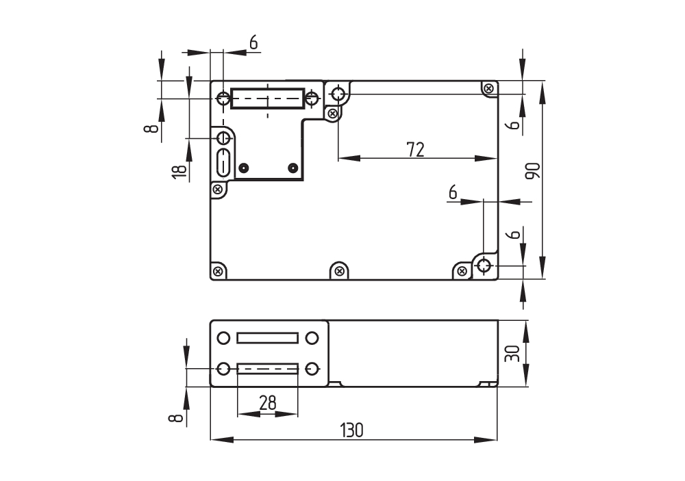
The tightening sequence of the cover screws must be observed. This can be found in the attached drawing in the “Pictures” tab. |
机械参数 - 连接技术
| 电缆入口 |
4 x M16 x 1,5 |
| 连接器 |
笼式接线夹 |
| 线缆截面,最小 |
.25 mm² |
| 电缆截面,最大 |
1.5 mm² |
| 注(电缆截面) |
包括导体套管在内的所有指标。 |
| 允许的电缆类型 |
实心单线 实心多导线 可调 |
机械参数 - 尺寸
| 传感器长度 |
30 mm |
| 传感器宽度 |
130 mm |
| 传感器高度 |
90 mm |
环境条件
| 防护等级 |
IP67 |
| 工作环境温度 |
-30 ... +60 °C |
| 储存和运输温度 |
-30 ... +85 °C |
| 注(相对湿度) |
无冷凝 不结冰 |
| 防护等级 |
II |
| 最大允许安装海拔高度 |
2,000 m |
环境条件 - 绝缘值
| 额定绝缘电压 Ui |
250 VAC |
| 额定冲击耐受电压 Uimp |
4 kV |
电气参数
| 热测试电流 |
6 A |
| 额定控制电压 |
24 VAC/DC |
| 要求额定短路电流 |
1,000 A |
| 电力功率消耗,最大 |
10 W |
| 开关元件 |
NO触点,NC触点 |
| 开关原理 |
缓动型,肯定断开常闭触点 |
| 开关频率 |
1,000 /h |
| 触点材料,电气 |
银 |
电气参数 - 线圈控制
| 磁铁闭合时间 |
100 % |
| 测试脉冲持续时间, 最大 |
5 ms |
| 测试脉冲间隔, 最低限度 |
50 ms |
电气参数 - 安全触点
| 电压,应用类别 AC-15 |
230 VAC |
| 电流,应用类别 AC-15 |
4 A |
| 电压,应用类别 DC-13 |
24 VDC |
| 电流,应用类别 DC-13 |
2.5 A |
电气参数 - 辅助触点
| 电压,应用类别 AC-15 |
230 VAC |
| 电流,应用类别 AC-15 |
4 A |
| 电压,应用类别 DC-13 |
24 VDC |
| 电流,应用类别 DC-13 |
2.5 A |
其他数据
| 备注(应用) |
滑动安全门 可拆卸防护门 铰链式安全防护装门 |
发货范围
| 发货范围 |
操动件#必须单独订购. |
注意
| 注(紧急出口) |
紧急出口用于需要干预已经锁定的危险区域时。 通过按下红色按钮紧急解锁 通过拉锁定按钮重置 可以从顶部(订货后缀 -TD)或后部(订货后缀 -TU)安装 在后侧 |
| 注(手动解锁) |
用于维护,安装,等等 使用M5三角钥匙来进行手动解锁,可作为附件 可以从顶部(订货后缀 -ED)或后部(订货后缀 -EU)安装 在侧面 |
| 注(紧急出口,手动解锁) |
手动解锁和紧急出口的组合,安装方向不同,仅适用于以下型号:-ED/-TU和-TD/-EU |
语言条件
数据表
操作指南及符合性声明(短篇)
CCC认证
通用信息
SISTEMA-VDMA 数据库
下载最新版本的Adobe Reader
产品图片(单独目录照片)
尺寸图 基本组件
尺寸图 基本组件
尺寸图 其他
尺寸图 其他
开关行程图
101175171 AZM 161-STS30-01
- 锁定把手
- 适合各种防护
- 最高 110 °C
101175178 AZM 161-STS30-02
- 锁定把手
- 适合各种防护
- 最高 110 °C
101175481 AZM 161-STS30-03
- 锁定把手
- 适合各种防护
- 最高 110 °C
101175486 AZM 161-STS30-04
- 锁定把手
- 适合各种防护
- 最高 110 °C
101175490 AZM 161-STS30-05
- 锁定把手
- 适合各种防护
- 最高 110 °C
101175491 AZM 161-STS30-06
- 锁定把手
- 适合各种防护
- 最高 110 °C
101173764 AZM 161-STS30-07
- 锁定把手
- 适合各种防护
- 最高 110 °C
101173763 AZM 161-STS30-08
- 锁定把手
- 适合各种防护
- 最高 110 °C
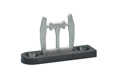
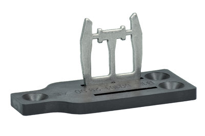
151145117 AZM161-B1
- 直操动件
- 特别适合滑动门
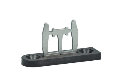
101144416 操动件 AZM 161-B1E
- 直操动件
- 特别适合滑动门

101171859 操动件 AZM 161-B1ES
- 直操动件
- 特别适合滑动门

101175431 操动件 AZM 161-B1F
- 直操动件
- 特别适合滑动门
101171125 操动件 AZM 161-B1S
- 直操动件
- 特别适合滑动门

101170375 操动件 AZM 161-B6S
- 非常小的操动半径
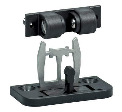
101173089 AZM 161-B1-2053 改装套件
- 直操动件
- 特别适合滑动门
- 可调整的滚珠锁定

101164100 AZM 161-B1-1747 改装套件
- 带保持磁铁直操动件
- 特别适合滑动门

101178199 AZM 161-B1-2024
- 带密封条的直操动件
- 特别适合滑动门

101176642 AZM 161-B1-2177 改装套件
- 带中心对准直操动件
- 特别适合滑动门

101174113 AZM 161-B6-2177 带中心定位
- 非常小的操动半径
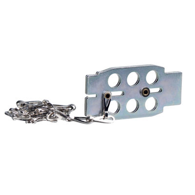
101110500 停工上锁标签 SZ 16/335
- 为防止意外关闭,比如在维修时
- 复杂工厂环境
- 防止开关操作
- 最多可以固定6个挂锁
- 停工标记可以用链条固定在安全开关附近。
清单
- 1 About this document
- 1.1 Function
- 1.2 Target group of the operating instructions: authorised qualified personnel
- 1.3 Explanation of the symbols used
- 1.4 Appropriate use
- 1.5 General safety instructions
- 2 Product description
- 2.1 Ordering code
- 2.2 Special versions
- 2.3 Purpose
- 2.4 Warning about misuse
- 2.5 Exclusion of liability
- 2.6 Technical Data
- 3 Mounting
- 3.1 General mounting instructions
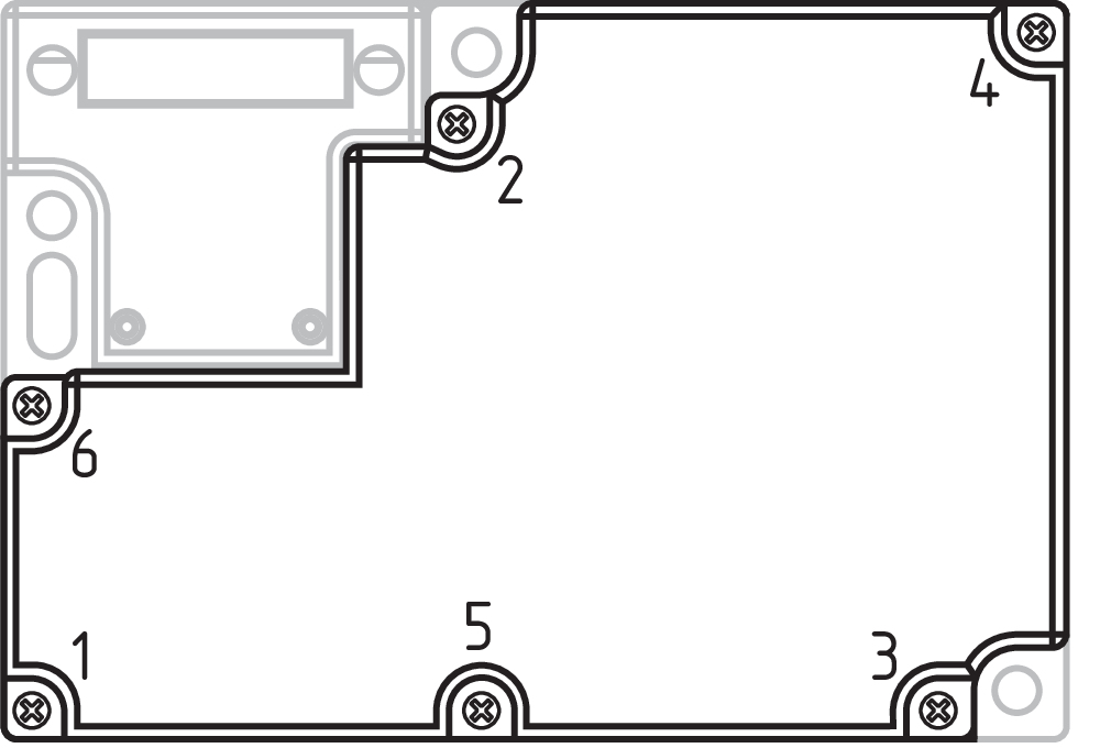
- 3.2 Dimensions
- 3.3 Manual release
- 3.4 Emergency release (ordering suffix -N)
- 3.5 Emergency Exit
- 4 Electrical connection
- 4.1 General information for electrical connection
- 4.2 Contact Options
- 5 Set-up and maintenance
- 6 Disassembly and disposal
- 6.1 Disassembly
- 6.2 Disposal
1 About this document
1.1 Function
This document provides all the information you need for the mounting, set-up and commissioning to ensure the safe operation and disassembly of the switchgear. The operating instructions enclosed with the device must always be kept in a legible condition and accessible.
1.2 Target group of the operating instructions: authorised qualified personnel
All operations described in the operating instructions manual must be carried out by trained specialist personnel, authorised by the plant operator only.
Please make sure that you have read and understood these operating instructions and that you know all applicable legislations regarding occupational safety and accident prevention prior to installation and putting the component into operation.
The machine builder must carefully select the harmonised standards to be complied with as well as other technical specifications for the selection, mounting and integration of the components.
The information contained in this operating instructions manual is provided without liability and is subject to technical modifications.
1.3 Explanation of the symbols used
- Information, hint, note: This symbol is used for identifying useful additional information.
- Caution: Failure to comply with this warning notice could lead to failures or malfunctions.
Warning: Failure to comply with this warning notice could lead to physical injury and/or damage to the machine.
1.4 Appropriate use
The Schmersal range of products is not intended for private consumers.
The products described in these operating instructions are developed to execute safety-related functions as part of an entire plant or machine. It is the responsibility of the manufacturer of a machine or plant to ensure the correct functionality of the entire machine or plant.
The safety switchgear must be exclusively used in accordance with the versions listed below or for the applications authorised by the manufacturer. Detailed information regarding the range of applications can be found in the chapter "Product description".
1.5 General safety instructions
The user must observe the safety instructions in this operating instructions manual, the country specific installation standards as well as all prevailing safety regulations and accident prevention rules.
- Further technical information can be found in the Schmersal catalogues or in the online catalogue on the Internet: products.schmersal.com.
2 Product description
2.1 Ordering code
| Product type description: AZM161 (1)-(2)(3)K(4)-(5)/(6)-(7)(8) |
| (1) | |
| SK | Screw connection |
| CC | Cage clamps |
| ST | Connector plug M12 |
| (2) | |
| 11/03 | Magnet: 1 NO contact, 1 NC contact / Actuator: 3 NC contacts with connector plug |
| 12/03 | Magnet: 1 NO contact, 2 NC contact / Actuator: 3 NC contacts |
| 12/11 | Magnet: 1 NO contact, 2 NC contacts / Actuator: 1 NO contact, 1 NC contact with connector plug |
| 11/12 | Magnet: 1 NO contact, 1 NC contacts / Actuator: 1 NO contact, 2 NC contact with connector plug |
| 12/12 | Magnet: 1 NO contact, 2 NC contacts / Actuator: 1 NO contact, 2 NC contacts |
| (3) | |
| without | Latching force 5 N |
| R | Latching force 30 N |
| (4) | |
| without | Power to unlock |
| A | Power to lock |
| (5) | |
| without | Lateral manual release |
| ED | Manual release on the cover side |
| EU | Manual release on the back side |
| (6) | |
| T | Lateral emergency exit |
| TD | Emergency exit on the cover side |
| TU | Emergency exit on the back side |
| N | Emergency release |
| (7) | |
| 024 | Us: 24 VAC/DC |
| 110/230 | Us: 110/230 VAC |
| (8) | |
| without | without LED |
| G | with LED (only for Us: 24 VAC/DC) |
2.2 Special versions
For special versions, which are not listed in the ordering code, these specifications apply accordingly, provided that they correspond to the standard version.
2.3 Purpose
The solenoid interlock has been designed to prevent in conjunction with the control part of a machine, movable safety guards from being opened before hazardous conditions have been eliminated.
- Interlocks with power to lock principle may only be used in special cases after a thorough evaluation of the accident risk, since the safety guard can be opened immediately on failure of the power supply or upon activation of the main switch.
- The safety switchgears are classified according to EN ISO 14119 as type 2 interlocking devices.
- The user must evaluate and design the safety chain in accordance with the relevant standards and the required safety level.
- The entire concept of the control system, in which the safety component is integrated, must be validated to the relevant standards.
2.4 Warning about misuse
- In case of improper use or manipulation of the safety switchgear, personal hazards or damages to machinery or plant components cannot be excluded. There are no residual risks, provided that the safety instructions as well as the instructions regarding mounting, commissioning, operation and maintenance are observed.
2.5 Exclusion of liability
We shall accept no liability for damages and malfunctions resulting from defective mounting or failure to comply with the operating instructions manual. The manufacturer shall accept no liability for damages resulting from the use of unauthorised spare parts or accessories.
For safety reasons, invasive work on the device as well as arbitrary repairs, conversions and modifications to the device are strictly forbidden, the manufacturer shall accept no liability for damages resulting from such invasive work, arbitrary repairs, conversions and/or modifications to the device.
2.6 Technical Data
许可 - 标准
| 证书 |
IFA cULus CCC |
总体数据
| 标准型 |
EN ISO 13849-1 EN ISO 14119 EN IEC 60947-5-1 |
| 编码等级,依据EN ISO 14119 |
低 |
| 工作原理 |
机电 |
| 外壳材料 |
塑料,玻璃纤维加固热塑塑料,自熄灭 |
| 毛重 |
480 g |
总体数据 - 产品特性
| 通电解锁 |
是 |
| 紧急逃逸 |
是 |
| 手动解锁 |
是 |
| 操动方向数量 |
3 |
| 辅助触点数量 |
2 |
| 安全触点数量 |
4 |
安全评估
| 标准型 |
EN ISO 13849-1 |
| 性能水平,最高 |
c |
| 类别 |
1 |
| B10D 常闭触点 (NC) |
2,000,000 操作 |
| 注意 |
按要求提供电气寿命。 |
| B10D 常开触点(NO) |
1,000,000 操作 |
| 注意 |
在10% Ie 及阻性负载时 |
| 任务时间 |
20 年 |
安全评估 - 故障排除
| 请注意: |
可用于允许排除单通道机构危险损坏的故障,并确保有足够的防操纵保护。 |
| 性能水平,最高 |
d |
| 类别 |
3 |
| 注意 |
用于双通道,并配有合适的逻辑单元。 |
| 任务时间 |
20 年 |
安全评估 - 防护锁定
| 性能水平,最高 |
e |
| 注意 (绩效水平) |
防护装置锁定功能的安全分类信息在 "操作说明 "或 "操作和安装 "说明中均有记载。 |
机械参数
| 机械寿命,最少 |
1,000,000 操作 |
| 操动方向上的操动件动作 |
5.5 mm |
| 保持力 FZh 按照 EN ISO 14119 |
2,000 N |
| 锁紧力 Fmax, 最大 |
2,600 N |
| 锁定力 |
30 N |
| 肯定断开行程 |
10 mm |
| 每个 NC 触点的正断开力, 最小力 |
10 N |
| 肯定断开操作力,最小 |
20 N |
| 操动速度,最大 |
2 m/s |
| 安装 |
螺钉 |
| 固定螺丝类型 |
3x M5 |
| 螺钉头类型 |
平头螺钉 |
| 箱盖紧固螺钉的拧紧扭矩 |
0.6 Nm |
| 注意 |
The tightening sequence of the cover screws must be observed. This can be found in the attached drawing in the “Pictures” tab. |
机械参数 - 连接技术
| 电缆入口 |
4 x M16 x 1,5 |
| 连接器 |
笼式接线夹 |
| 线缆截面,最小 |
.25 mm² |
| 电缆截面,最大 |
1.5 mm² |
| 注(电缆截面) |
包括导体套管在内的所有指标。 |
| 允许的电缆类型 |
实心单线 实心多导线 可调 |
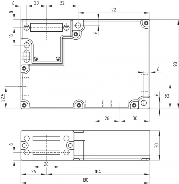
机械参数 - 尺寸
| 传感器长度 |
30 mm |
| 传感器宽度 |
130 mm |
| 传感器高度 |
90 mm |
环境条件
| 防护等级 |
IP67 |
| 工作环境温度 |
-30 ... +60 °C |
| 储存和运输温度 |
-30 ... +85 °C |
| 注(相对湿度) |
无冷凝 不结冰 |
| 防护等级 |
II |
| 最大允许安装海拔高度 |
2,000 m |
环境条件 - 绝缘值
| 额定绝缘电压 Ui |
250 VAC |
| 额定冲击耐受电压 Uimp |
4 kV |
电气参数
| 热测试电流 |
6 A |
| 额定控制电压 |
24 VAC/DC |
| 要求额定短路电流 |
1,000 A |
| 电力功率消耗,最大 |
10 W |
| 开关元件 |
NO触点,NC触点 |
| 开关原理 |
缓动型,肯定断开常闭触点 |
| 开关频率 |
1,000 /h |
| 触点材料,电气 |
银 |
电气参数 - 线圈控制
| 磁铁闭合时间 |
100 % |
| 测试脉冲持续时间, 最大 |
5 ms |
| 测试脉冲间隔, 最低限度 |
50 ms |
电气参数 - 安全触点
| 电压,应用类别 AC-15 |
230 VAC |
| 电流,应用类别 AC-15 |
4 A |
| 电压,应用类别 DC-13 |
24 VDC |
| 电流,应用类别 DC-13 |
2.5 A |
电气参数 - 辅助触点
| 电压,应用类别 AC-15 |
230 VAC |
| 电流,应用类别 AC-15 |
4 A |
| 电压,应用类别 DC-13 |
24 VDC |
| 电流,应用类别 DC-13 |
2.5 A |
其他数据
| 备注(应用) |
滑动安全门 可拆卸防护门 铰链式安全防护装门 |
Note about the safety classification
- Safety classification of the interlocking function
Basically suitable up to Cat. 1 / PL c.
With 2-channel usage with fault exclusion mechanism (if a fault exclusion to the 1-channel mechanics is authorised) and suitable logic applicable up to Cat. 3 / PL d

(Determined values can vary depending on the application-specific parameters hop, dop and tcycle as well as the load.)
If multiple safety components are wired in series, the Performance Level to EN ISO 13849-1 will be reduced due to the restricted error detection under certain circumstances.
- Safety classification of the guard locking function
If the device is used as an interlock for personal safety, a safety classification of the guard locking function is required. When classifying the interlock function, a distinction must be made between monitoring of the interlock function (locking function) and controlling the unlocking function. The following safety classification of the unlocking function is based on the application of the principle of safety energy disconnection for the solenoid supply.
- The classification of the unlocking function is only valid for devices with monitored guard locking function and in the power to unlock version (see ordering code).
A fault exclusion for the guard locking function can be assumed by an external safety energy disconnection. In this case, the guard locking function does not have an effect on the failure probability of the unlock function. The safety level of the unlock function is determined exclusively by the external safety power shutdown.
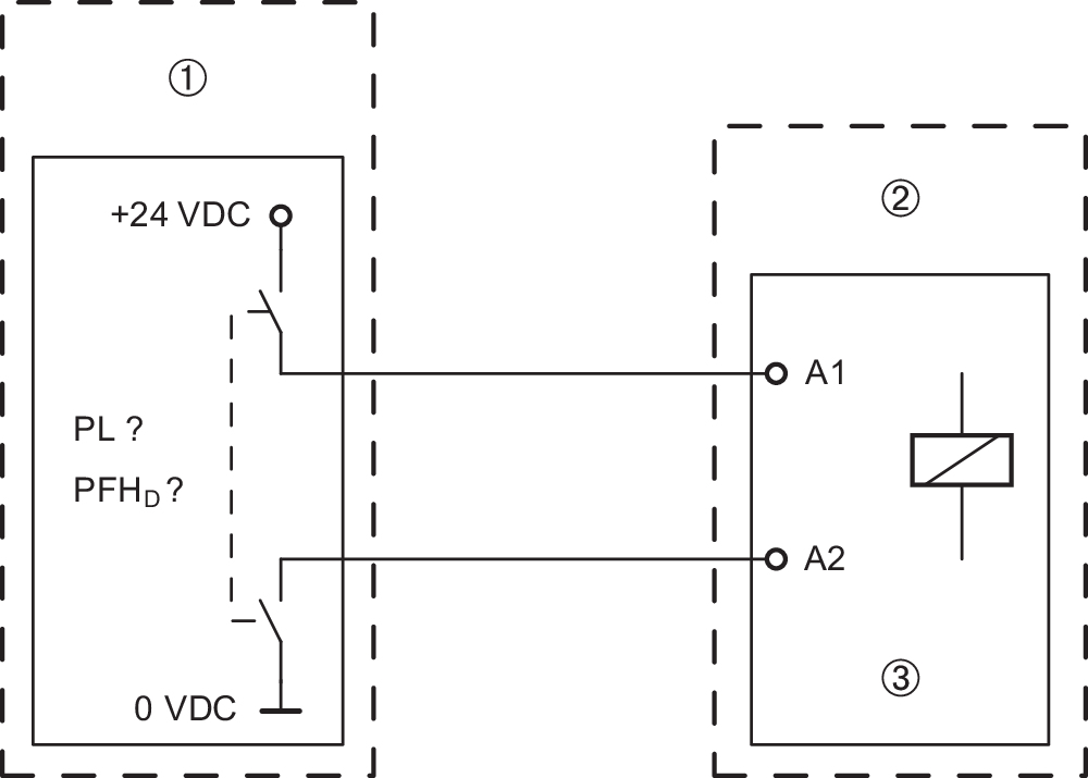
| Legend | |
|---|---|
| ¢ | Safety power shutdown |
| ƒ | Solenoid interlock |
| ¥ | Guard locking function |
- Fault exclusion with regard to wiring routing must be observed.
- If for a certain application the power to unlock version of a solenoid interlock cannot be used, for this exception an interlock with power to lock can be used if additional safety measure need to be realised that have an equivalent safety level.
UL notice
- Use Type 4X (Indoor Use) and 12 connector fittings. Tightening torque rating: 4.4 lb in.
3 Mounting
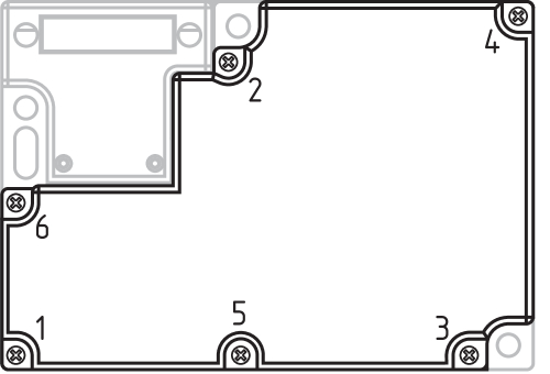
3.1 General mounting instructions
- Please observe the remarks of the standards EN ISO 12100, EN ISO 14119 and EN ISO 14120.
Three mounting holes are provided for fixing the enclosure. The solenoid interlock is double insulated. The use of an earth wire is not authorised. The solenoid interlock must not be used as an end stop. Any mounting position. The mounting position however must be chosen so that the ingress of dirt and soiling in the used opening is avoided. Unused actuator openings must be sealed with slot sealing plugs.
- The actuator must be permanently fitted to the safety guards and protected against displacement by suitable measures (tamperproof screws, gluing, drilling of the screw heads).
3.2 Dimensions
All measurements in mm.
3.3 Manual release
(for set-up, maintenance, etc.)
Manual release is realised by turning the triangular key by 180° (M5 triangular key available as accessory), so that the locking bolt is pulled into the unlocking position. Please ensure that jamming by external influence on the actuator is avoided. The normal locking function is only restored after the triangular key has been returned to its original position. After being put into operation, the manual release must be secured by installing the plastic cover, which is included in delivery.
| Lateral manual release | Manual release on the cover side or on the rear side (ordering suffix -ED/-EU) |
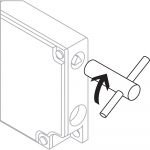 |  |
Triangular key TK-M5 (101100887) available as accessory.
3.4 Emergency release (ordering suffix -N)
(Fitting and actuation only from outside the hazardous area)
- The emergency release should only be used in an emergency. The solenoid interlock should be installed and/or protected so that an inadvertent opening of the interlock by an emergency release can be prevented. The emergency release must be clearly labelled that it should only be used in an emergency. The label can be used that was included in the delivery.
To activate the emergency release in case of an emergency, the orange lever must be turned to the stop in the direction marked by the arrow. In this position, the safety guard can be opened. The lever is latched and cannot be returned to its original position. To cancel the blocking condition, the central mounting screw must be loosened to such extent that the lever can be turned back into its original position. The screw must then be re-tightened.
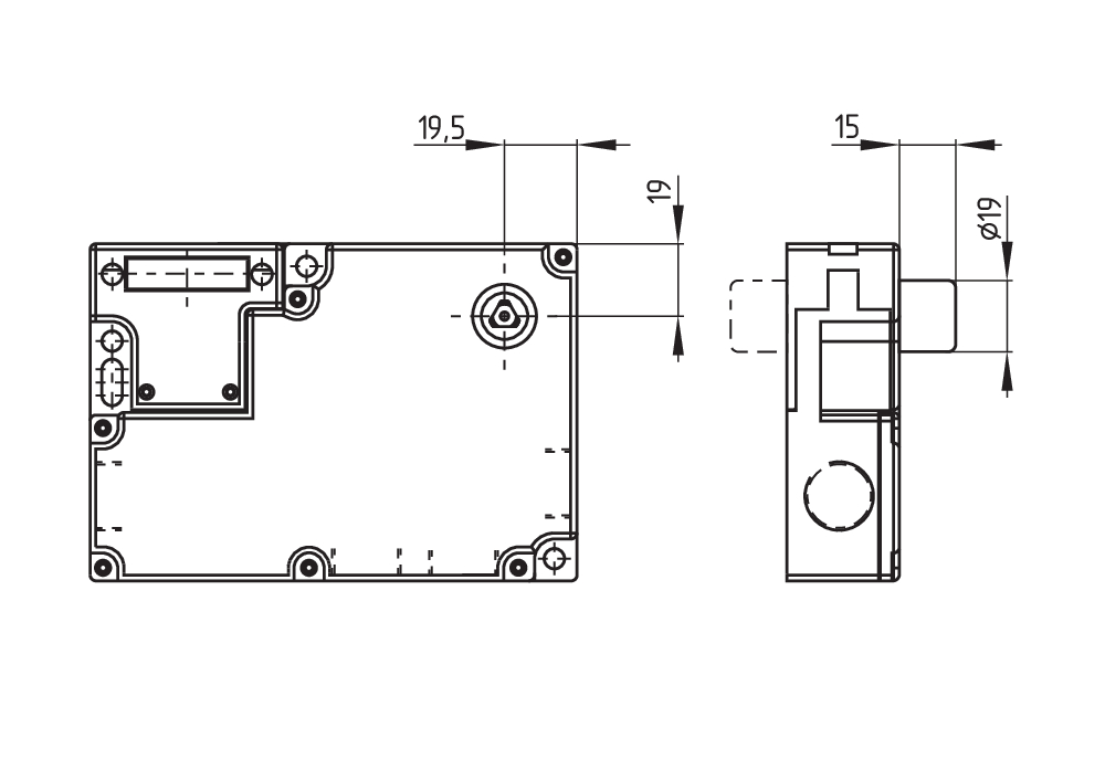
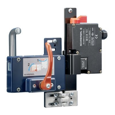
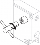
3.5 Emergency Exit
(Fitting and actuation only from within the hazardous area)
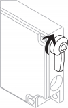
To activate the emergency exit of the T version in case of an emergency, the orange lever must be turned to the stop in direction marked by the arrow. The emergency exit function of the TD and TU versions is activated by pressing the red pushbutton. In this position, the safety guard can be opened. The blocking condition is cancelled by turning the lever in opposite direction or by pulling back the pushbutton. In unlocked position, the safety guard is protected against unintentional closing.
| Lateral emergency exit (ordering suffix -T) | Emergency exit on the cover side or on the rear side (ordering suffix -TD/-TU) |
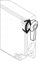 | 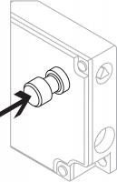 |
4 Electrical connection
4.1 General information for electrical connection
- The electrical connection may only be carried out by authorised personnel in a de-energised condition.
- If the risk analysis indicates the use of a monitored interlock they are to be connected in the safety circuit with the contacts indicated with the symbol >.
Appropriate cable glands with a suitable degree of protection are to be used. Remove the walls of the mounting holes by inserting the cable entry. All plastic residues must be removed from the switch compartment.

- Puncturing the wall of the holes with auxiliary tools (e.g. screwdriver) can cause damage.
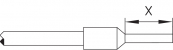
Settle length x of the conductor:
- on cage clamps (CC) of type s or f: 5 ... 6 mm
- on screw terminals (SK): 7 mm
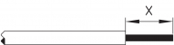 |  |
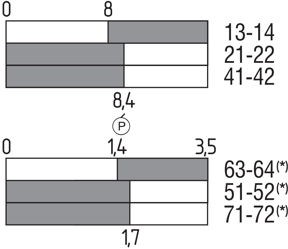
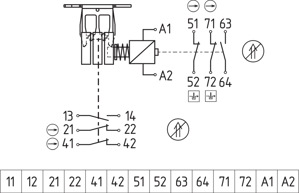
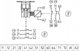
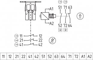
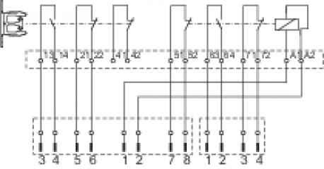
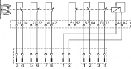
4.2 Contact Options
Contacts shown in a de-energised condition and with the actuator inserted.
| Power to unlock | Power to lock |
|---|---|
| AZM 161SK-12/12... und AZM 161CC-12/12... | |
 |  |
| AZM 161SK-12/03... und AZM 161CC-12/03... | |
 |  |
| Key | |
|---|---|
| B | Positive break NC contact |
| > | Monitoring the interlock according to EN ISO 14119 |
| H | Actuated |
| I | Not actuated |
| AZM 161ST-../.. with connector AZM 161ST-12/11... | AZM 161ST-11/12... |
 |  |
| AZM 161ST-11/03... | |
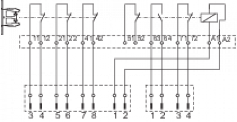 |

Integrated contact kit 12/12 G (with LED)
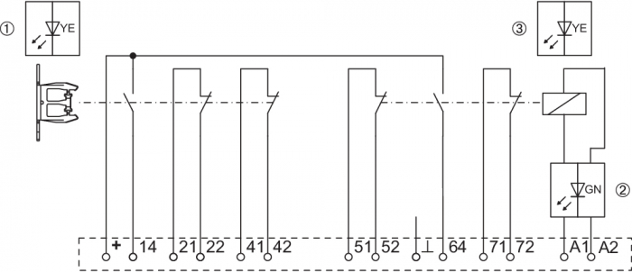
The 24 V are led internally to contacts 13 and 63. The corresponding signals of the LED display can also be tapped at terminals 14 or 64.
Integrated contact kit 12/03 G (with LED)

The 24 V are led internally to contacts 11 and 63. The corresponding signals of the LED display can also be tapped at terminals 12 or 64.
| Legend | |
|---|---|
| 1 | Door closed |
| 2 | Solenoid on |
| 3 | Door locked |
| Power to unlock | ||||
|---|---|---|---|---|
| System condition | Magnet control | LED | ||
| Power to unlock | yellow ¢ | green ƒ | yellow ¥ | |
| Door open | 24 V (0 V) | Off | On | Off |
| Door closed, actuator inserted, not locked | 24 V | On | On | Off |
| Door closed, actuator inserted and locked | 0 V | On | Off | On |
| Power to lock | ||||
|---|---|---|---|---|
| System condition | Magnet control | LED | ||
| Power to lock | yellow ¢ | green ƒ | yellow ¥ | |
| Door open | 0 V (24 V) | Off | Off | Off |
| Door closed, actuator inserted, not locked | 0 V | On | Off | Off |
| Door closed, actuator inserted and locked | 24 V | On | On | On |
5 Set-up and maintenance
The safety function of the safety components must be tested. In the case of correct installation and adequate use, the safety switchgear features maintenance-free functionality. A regular visual inspection and functional test, including the following steps, is recommended:
- Check fixation of the safety switch and the actuator.
- Fitting and integrity of the cable connections.
- Remove particles of dust and soiling.
- Adequate measures must be taken to ensure protection against tampering either to prevent tampering of the safety guard, for instance by means of replacement actuators.
- Damaged or defective components must be replaced.
6 Disassembly and disposal
6.1 Disassembly
The safety switchgear must be disassembled in a de-energised condition only.
6.2 Disposal
- The safety switchgear must be disposed of in an appropriate manner in accordance with the national prescriptions and legislations.
| UK Declaration of Conformity |  |
| Company: | K.A. Schmersal GmbH & Co. KG Möddinghofe 30 42279 Wuppertal Germany Internet: www.schmersal.com |
| Declaration: | We hereby, under sole responsibility, certify that the hereafter described components both in their basic design and construction conform to the relevant statutory requirements, regulations and designated standards of the United Kingdom. |
| Name of the component: | AZM 161 |
| Type: | See ordering code |
| Description of the component: | Interlocking device with electromagnetic interlock for safety functions |
| Relevant legislation: | Supply of Machinery (Safety) Regulations | 2008 |
| Electromagnetic Compatibility Regulations | 2016 | |
| The Restriction of the Use of Certain Hazardous Substances in Electrical and Electronic Equipment Regulations | 2012 |
| Designated standards: | EN 60947-5-1:2017 + AC:2020 EN ISO 14119:2013 |
| UK-Importer / Person authorised for the compilation of the technical documentation: | Schmersal UK Ltd. Paul Kenney Unit 1, Sparrowhawk Close Enigma Business Park Malvern, Worcestershire, WR14 1GL |
| Place and date of issue: | Wuppertal, August 23, 2023 |
 |
| Authorised signature Philip Schmersal Managing Director |
| EU Declaration of Conformity | |
| Original | K.A. Schmersal GmbH & Co. KG Möddinghofe 30 42279 Wuppertal Germany Internet: www.schmersal.com |
| Declaration: | We hereby certify that the hereafter described components both in their basic design and construction conform to the applicable European Directives. |
| Name of the component: | AZM 161 |
| Type: | See ordering code |
| Description of the component: | Interlocking device with electromagnetic interlock for safety functions |
| Relevant Directives: | Machinery Directive | 2006/42/EC |
| EMC-Directive | 2014/30/EU | |
| RoHS-Directive | 2011/65/EU |
| Applied standards: | EN 60947-5-1:2017 + AC:2020 EN ISO 14119:2013 |
| Person authorised for the compilation of the technical documentation: | Oliver Wacker Möddinghofe 30 42279 Wuppertal |
| Place and date of issue: | Wuppertal, August 23, 2023 |
| |
| Authorised signature Philip Schmersal Managing Director |
施迈赛工业开关制造(上海)有限公司, 上海市青浦区漕盈路3336号,
所涉及的详细信息和数据已经过仔细检查。 图像可能与原始图像有所不同。 您可在说明书中进一步获得技术数据。 可能会有技术修改和错误。
生成日期 2025/2/12 下午10:51