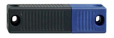
AST LC ST-AS
AST LC ST-AS
Downloads
- AS-i connection, connector plug M12, 4-pole
- NOTICE: Not available!
- Input module for 2 monitored PNP semiconductor outputs for safety light curtains and light grids
- Thermoplastic enclosure
- AS-Interface LED and status display
- 86,5 mm x 28 mm x 28 mm
- Long life
- Integrated AS-Interface
Ordering data
| Note (Delivery capacity) |
Not available! |
| Product type description |
AST LC ST-AS |
| Article number (order number) |
101182561 |
| EAN (European Article Number) |
4030661317649 |
| eCl@ss number, version 12.0 |
27-24-26-04 |
| eCl@ss number, version 11.0 |
27-24-26-04 |
| eCl@ss number, version 9.0 |
27-24-26-04 |
| ETIM number, version 7.0 |
EC001599 |
| ETIM number, version 6.0 |
EC001599 |
Approvals - Standards
| Certificates |
cULus |
General data
| Standards |
EN 50295 EN ISO 13849-1 EN IEC 61508 EN IEC 61496-1 |
| Connector (electric) |
AS-i connection: connector plug M12, 4-pole |
| Housing material |
Plastic, glass-fibre reinforced thermoplastic, self-extinguishing |
| Reaction time, maximum |
20 ms |
| Gross weight |
185 g |
General data - Features
| Cross-circuit detection |
Yes |
| Integral system diagnostics, status |
Yes |
| Number of pre-wired cable |
2 |
| Safety classification |
| Vorschriften |
EN IEC 61508 |
| Performance Level, up to |
e |
| Category |
4 |
| PFH value |
1.74 x 10⁻⁹ /h |
| Safety Integrity Level (SIL), suitable for applications in |
3 |
| Mission time |
20 Year(s) |
Mechanical data - Dimensions
| Diameter of sensor |
28 mm |
| Height of sensor |
86.5 mm |
Ambient conditions
| Degree of protection |
IP67 |
| Ambient temperature |
-25 ... +60 °C |
| Storage and transport temperature |
-25 ... +85 °C |
| Relative humidity, minimum |
30 % |
| Relative humidity, maximum |
95 % |
| Note (Relative humidity) |
non-condensing |
| Protection class |
II |
Ambient conditions - Insulation values
| Rated insulation voltage Ui |
32 VDC |
| Rated impulse withstand voltage Uimp |
0.8 kV |
| Overvoltage category |
III |
| Degree of pollution |
3 |
Electrical data
| Current consumption |
50 mA |
Electrical data - AS Interface
| Rated operating voltage |
26.5 ... 31.6 VDC (Protection against polarity reversal) |
Electrical data - AS-Interface specification
| AS-i Version |
V 2.1 |
| AS-i Profile |
S-0.B.F.E |
| AS-i, IO-Code |
0x7 |
| AS-i, ID-Code |
0xB |
| AS-i, ID-Code1 |
0xF |
| AS-i, ID-Code2 |
0xE |
| AS-i Input, Channel 1 |
Data bits DI 0 / DI 1 = dynamic code transmission |
| AS-i Input, Channel 2 |
Data bits DI 2 / DI 3 = dynamic code transmission |
| AS-i Outputs, DO 0 … DO 3 |
No Function |
| AS-i Parameter bits, P0 ... P3 |
No function |
| AS-i Parameter bits, P3 |
Authorised operation canal 1 + 2 |
| Note (AS-i Parameter bits) |
Set the parameter outputs to "1111" (0xF) |
| AS-i Input module address |
0 |
| Note (AS-i Input module address) |
Preset to address 0, can be changed through AS-interface bus master or hand-held programming device |
Status indication
| Note (LED switching conditions display) |
(1) LED green: Supply voltage (2) LED red: Communication error (3) LED yellow: Enabling status OSSD 1/2 |
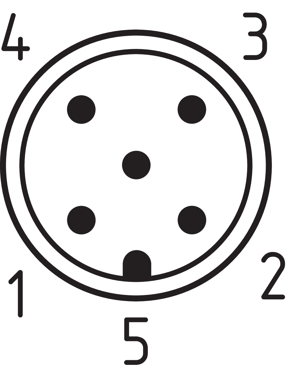
Pin assignment
| Connection |
ST1 male connector / power supply for Safety light grids and curtains |
| PIN 1 |
24 VDC |
| PIN 2 |
n.c. |
| PIN 3 |
GND |
| PIN 4 |
n.c. |
| PIN 5 |
FE (functional earth connection) |
| Connection |
ST2 female connector / Safety light grids and curtains |
| PIN 1 |
+ 24 VDC |
| PIN 2 |
OSSD 1 |
| PIN 3 |
GND |
| PIN 4 |
OSSD 2 |
| PIN 5 |
FE (functional earth connection) |
Wiring example
| Note (Wiring diagram) |
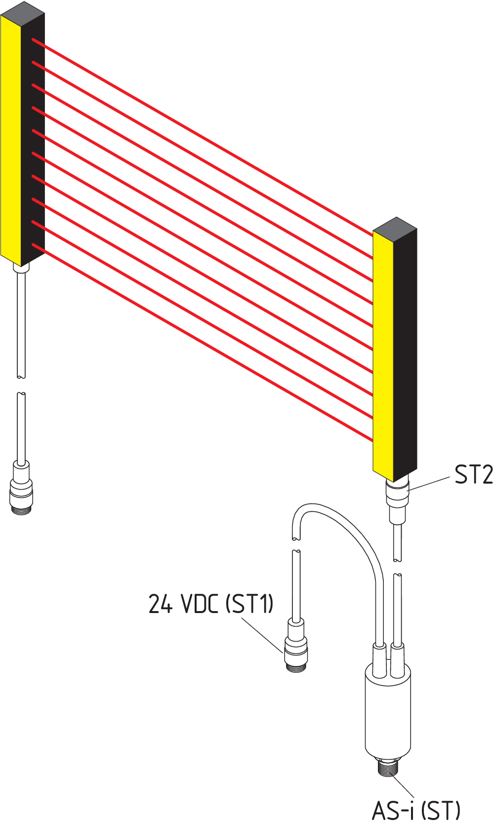
The Opto-Tube is directly connected to the receiver module (ST2). The receiver module is supplied with 24 V DC via the connector (ST1). The Opto-Tube itself is connected via the M12 connector (ST) to the AS-i network. Before hand the module has to be programmed with an individual address (1 - 31). The emitter module has to be wired up separately Please observe the corresponding SLC/SLG documentation (test signal). The wiring diagram shows an active optoelectronic device (AOPD) (type SLC/SLG 420) with a safety input module AST LC ST-AS (Opto-Tube) connected to the AS-i Safety at Work system. |
Language filter
Datasheet
Operating instructions and Declaration of conformity
UL Certificate
Download the latest version of Adobe Reader
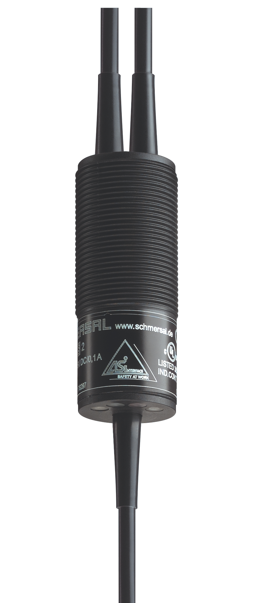
Product picture (catalogue individual photo)
Dimensional drawing basic component
Wiring example
Contact arrangement
Schmersal Canada Ltd., 29 Centennial Road, Unit 1, Orangeville, Ontario L9W 1R1 Canada
The details and data referred to have been carefully checked. Images may diverge from original. Further technical data can be found in the manual. Technical amendments and errors possible.
Generated on: 2025-06-07, 10:39 a.m.
.png?id=dd4d6d28421d06b6d1d6f7ffec683d49)
